Strength
Strength of a wooden body DKW F8, 1939. At least 28 people are standing on a moving car. Strength
(in physics and materials science) is the property of a material to resist destruction under the influence of internal stresses arising under the influence of external forces.
The property of a structure to fulfill its purpose without collapsing within a given time.
Classification
Strength is divided into static, under the influence of constant loads, dynamic and fatigue (endurance), which occurs under the action of cyclic variable loads.
For structures, a distinction is made between general strength—the ability of the entire structure to withstand loads without destruction—and local strength—the same ability of individual units, parts, and connections.
Quantitative consideration
Currently, when calculating strength, both calculations based on permissible stresses and calculations based on the permissible number of loading cycles are used. The main inequalities in the calculation of permissible stresses:
σ max ⩽ [ σ ] , τ max ⩽ [ τ ] , {\displaystyle \sigma _{max}\leqslant [\sigma ],\quad \tau _{max}\leqslant [\tau ],}
Where
- σ max {\displaystyle \sigma _{max}} and τ max {\displaystyle \tau _{max}} are the highest calculated normal and shear stresses, respectively;
- [ σ ] {\displaystyle [\sigma ]} and [ τ ] {\displaystyle [\tau ]} are permissible normal and shear stresses that are safe for the strength of the part.
Application
Ensuring the strength of machines, devices and structures is carried out as follows. At the stage of their design, a calculation or experimental assessment is made of the possibility of development of various types of destruction processes in the load-bearing elements of the designed structures: fatigue, brittle, quasi-static, destruction due to material creep, corrosion, wear during operation, etc. In this case, all possible under operating conditions of the structure, currently known mechanisms of destruction of the material from which its load-bearing elements are made. For a newly created class of machines or devices, the specified destruction mechanisms are identified at the stage of the research design cycle. Each of these destruction mechanisms is associated with a certain strength criterion - one or another characteristic of the physical state of the material of machine and apparatus elements, determined by calculation or experiment. For each of the strength criteria of the structural material, its limit values are experimentally established. Based on the limit values, the permissible values of these criteria are then determined. The latter are determined, as a rule, by dividing the limiting values of the strength criterion by the corresponding safety factor. The values of safety factors are assigned based on operating experience, taking into account the degree of responsibility of the designed structure, its estimated service life and the possible consequences of its destruction.
The safety factor values for different failure mechanisms are different. When calculating based on permissible stresses, they vary, as a rule, in the range of values from 1.05 (when ensuring the strength of elements of aircraft that have a short life cycle and are not intended to transport people) to 6 (when ensuring the strength of cables used in the structures of passenger elevators ). When calculating based on the permissible number of loading cycles, significantly larger values of these coefficients can be used. The calculation of the most critical and energy-intensive designs of machines and devices is regulated by industry norms and standards. As operating experience is accumulated, methods for studying the physical state of structures are developed, and methods for ensuring strength are improved, these norms and standards are periodically revised.
Destruction
Brittle and ductile fracture have different types of fractured surfaces. The nature of the defects gives an idea of what type of destruction is taking place. In brittle fracture, the surface is broken. In ductile fracture, the surface is tense (knits the fracture).
Fracture toughness
is a relative increase in tensile stresses at the mouth of a crack during its transition from a stable to an unstable stage of growth.[1]
Fracture toughness is closely related to the strength properties of the material. An increase in strength is accompanied by a decrease in ductility and fracture toughness. This is explained by the fact that high-strength materials have low energy absorbed during fracture, the level of which is determined by the amount of plastic deformation at the crack tip. For high-strength materials, the effect of increasing strength is significantly offset by a decrease in ductility, as a result of which fracture toughness decreases. Materials of medium and low strength generally have higher values at room temperature than high strength materials. As the temperature decreases, the strength increases and, under certain conditions, the behavior of a material of medium and low strength becomes the same as that of a high-strength material at room temperature. At low temperatures, fracture toughness testing can be performed on smaller specimens.
Modern calculation methods
To calculate the stress-strain state of a structure and determine its strength, modern high-tech technologies are used - computer engineering analysis systems based on the use of grid methods for solving problems of mathematical physics. Currently, one of the most effective and universal methods of this class is the finite element method (FEM).
The most common FE analysis systems are:
ANSYS - universal FE analysis system with built-in pre-/post-processor;
MSC.Nastran - universal FE analysis system with pre-/post-processor;
ABAQUS is a universal FE analysis system with a built-in pre-/post-processor;
NEiNastran - universal FE analysis system with FEMAP pre-/post-processor;
NX Nastran is a universal FE analysis system with FEMAP pre/post processor.
ru.wikipedia.org>
3.3. Determination of compressive strength
The strength of building materials is characterized by their tensile strength. The tensile strength is the stress corresponding to the load causing destruction of the material sample. The compressive strength for various materials ranges from 0.5 to 1000 MPa or more and is determined by the formula:
,
where Рbreak – destructive compressive force, kgf; F is the initial area of the sample, cm2.
There are destructive and non-destructive methods for determining the strength of building materials.
3.3.1 Destructive methods for determining the strength of building materials.
A destructive method for determining compressive strength is testing samples on mechanical or hydraulic presses (Fig. 3.3). For this purpose, samples in the form of cubes, cylinders, and prisms are used. Considering that the press readings are influenced by the shape, dimensions of the sample, the nature of its surface, the speed of application of the load and other factors, it is necessary to adhere to the standard test methods established for this material. The power of the press must be at least 1.25 times the breaking load on the sample. Disadvantages of the method: the bulkiness of the press, the need for power electricity, the destruction of samples, not the product material (there may be a significant difference between them).
Equipment and materials: hydraulic press, sample of building material, measuring ruler.
Progress
Samples are inspected and measured before testing. They must have the correct geometric shape and parallel opposite edges. The working cross-sectional area of the sample F, cm2, is determined as the arithmetic mean of the areas of both supporting faces, rounded to 0.1 cm2.
The sample is placed with one of the previously marked faces on the lower support plate of the press so that the axes of the sample and the plate coincide. The increase in load on the sample must occur smoothly and at a speed specified by the standard in relation to the type of press and the size of the samples. The number of samples must be at least three. The results obtained are entered into the table. 3.3.
3.3.1.a. Determination of the softening coefficient
The softening coefficient is the ratio of the strength of a material saturated with water to its strength in a dry state. This coefficient characterizes the water resistance of the material and varies within 0…1. For building structures located in water or operating in places of constant moisture, materials with a softening coefficient of less than 0.8 cannot be used, for wall materials - less than 0.6.
Softening coefficient:
,
where Rsat, Rdry are the compressive strength of samples in the water-saturated and dry states, respectively, MPa.
3.3.2. Non-destructive methods for determining the strength of building materials.
Non-destructive methods for assessing the strength of building materials are divided into mechanical and physical. They are based on the dependence of the strength of the material on some other physical and mechanical characteristic of the material
.
3.3.2.a. Mechanical non-destructive methods for determining the strength of a material.
Mechanical non-destructive methods are based on measurements:
a) the size of the imprint of stamps on concrete, obtained from pressing stamps using special devices (G. Khaidukov’s stamp, I.A. Fizdel’s hammer, etc.);
b) the ratio of the size of the imprints obtained by pressing the striker into the surface of the concrete and the imprint on the standard (K.P. Makarov hammer, Poldi, etc.);
c) the magnitude of elastic rebound (S.N. Borovoy gun, Schmidt sclerometer);
d) the strength of concrete by shooting (V.G. Skramtaev’s method - shooting from a revolver, SMP construction and installation pistol);
e) forces of separation of rods, disks from the material (Wolf device).
Instruments and materials: standard hammer Kashkarova K.P. (Fig. 3.4.); angular scale; concrete samples.
Strength is determined using a standard hammer from Kashkarov K.P. The hammer consists of a head, a body with a handle, a glass, a spring and a ball. The machine has holes through which standard rods made of class A-I steel are inserted.
Progress
The concrete sample is placed on a solid base with the tested edge facing up. A rod is inserted into the hammer and round imprints are made on the sample with several blows (5-6 times) of medium force. Each subsequent blow is made after 20mm. Using an angular scale, the diameters of imprints on concrete db and on a reference rod (de) are measured with an accuracy of 0.1 mm. determine the average value of db and de, from which the ratio db / de is calculated. Using the calibration curve (Fig. 3.5), the strength of concrete is determined. The results are entered in the table. 3.3.
The advantage of the method is the simplicity, portability of the device, and the ability to determine the strength directly in structures. The disadvantage of the method is the ability to determine strength only in the surface layer.
3.3.2.b. Physical non-destructive methods for determining the strength of materials.
Physical methods for testing the strength of concrete include ultrasonic pulse, resonance and radiometric methods, which make it possible to judge the quality of the tested concrete not only by its surface layer, but also by its internal structure.
With the resonance method, the properties of concrete are assessed by the dynamic modulus of elasticity and the logarithmic attenuation decrement.
The radiometric method for determining the basic physical and mechanical properties is based on the law of weakening of the flux of rays after their interaction with the test medium.
With the ultrasonic pulse method, the properties of concrete are judged by the speed of propagation of the ultrasonic pulse and the intensity of its attenuation.
Recently, devices based on measuring magnetic permeability, dielectric constant and electrical conductivity characteristics have also become widespread.
Progress
Preparing the device for operation:
- Set the discrete digital readout switches “x10”, “xIx”, “x0.1” to the “0” position, the “+200” toggle switch to the upper position, the “Delay” toggle switch to any position.
- Turn on the mains power switch, and the indicator lamp should light up;
- Lubricate the ends of the receiver and emitter sensors with technical petroleum jelly and press them against each other, and the indicator lamp for turning on the device should light up. After 3...10 s, the emitter should start working, which is accompanied by the appearance of a characteristic sound with a frequency of 30...40 Hz, and the indicator lamp lights up;
- Holding the ends of the device sensors with your fingers, push them apart. The indicator lamp should remain on until the distance between the ends of the sensors is at least 60...70mm;
- Check instrument correction. To do this, set the “+200” toggle switch to the lower position: press the pre-lubricated end surfaces of the sensors together and then rotate the “Correction” knob clockwise until the indicator lamp lights up.
Working with devices:
- press the ends of the sensors to the material being tested from opposite side faces;
- set the toggle switch “+200” to the upper position; if the indicator lamp lights up, the toggle switch returns to the lower position;
- The discrete count switch “+10” is turned clockwise until the indicator lamp lights up. When the indicator lamp lights up, turn the knob with the “+10” multiplier counterclockwise one position, the lamp should go out;
- The discrete count switch “хІх” is rotated clockwise until the indicator lamp lights up. When the indicator lamp lights up, turn the knob counterclockwise one position, the lamp should go out;
- The discrete count switch “x0.1” is rotated clockwise until the indicator lamp lights up. This completes the measurement. The readings of the toggle switch and the discrete count switch are taken (time is measured in microseconds).
Determine the speed of ultrasound passing through the sample
,
where V is the speed of propagation of ultrasound, m/s; l – sample thickness, mm; t – ultrasound propagation time, μs.
The strength of the material is determined from the calibration curve (Fig. 3.7) and the data is placed in the table. 3.3.
Table 3.3
| No. | Hydraulic press | Kashkarov's hammer | Concrete – 3M | |||||||||
| R, kgf | F, cm2 | Rcom, kgf/cm2 | Rcom, MPa | db | de | db/de | Rcom, MPa | l, mm | t, mm | V, mm | Rcom, MPa | |
According to the table. 3.3 we can conclude that it is advisable to use and harmonize destructive and non-destructive methods for determining the strength of building materials.
The ultrasonic device "Beton - 3M" is simple and reliable to use, but more modern devices, such as "Beton - 5" and "UK - 10PM", are also used.
Progress of work on the ultrasonic device "Concrete - 5".
Lubricate the ends of the sensor and emitter with technical petroleum jelly and attach them to the test sample from opposite side edges, respectively.
Set the “+200” toggle switch to the upper position. When the indicator signal appears, return the toggle switch to the down position. (If there is no signal, stop the toggle switch in the upper position). Turn the switch with a resolution of 200 μs clockwise until the signal appears. When a signal appears, turn the switch clockwise one position. The indicator arrow should turn to the “0” position. Turn the switch with a reading resolution of 20 μs clockwise until the signal appears. When it appears, turn the switch knob counterclockwise one position. The indicator arrow should move to the “0” position. Turn the switch with a reading resolution of 2 µs clockwise until the signal appears. When the indication appears, turn the switch knob counterclockwise one position, and the indicator signal should be absent.
Turn the “correction” knob clockwise until a signal appears, which corresponds to a readout resolution of 0.1 μs. Take readings from the discrete count and “correction” switches.
After work, return all knobs and toggle switches to zero positions. We substitute the value of the time of passage of the ultrasonic wave through the sample array into the speed formula, calculate it and, using the V-Rcom dependence graph, determine the strength of the sample.
We put all the results in the table. 3.3.
OPERATING PROCEDURE OF ULTRASONIC
UK-10 IM DEVICE
Install the search heads through a layer of contact lubricant respectively on the material sample. An image of the received ultrasonic signal in the form of a wave should appear on the screen of cathode ray tube I (ETL).
By rotating the signal gain adjustment knob 2 to the left, we move the beginning of the wave until it aligns with the beginning of the scan line. On digital display panel 3 – “counting mode” we record the time of passage of the ultrasonic wave through the sample array in the ISS. We substitute the time value into the speed formula and use the calibration curve to determine the strength of the sample.
TOPICS FOR INDEPENDENT RESEARCH
- Study of the dependence of water absorption of a material on the type and nature of porosity.
- Study of the dependence of the strength of materials on the type and nature of porosity.
- Study of the dependence of the average density of materials on their porosity.
- Addiction Research
for reference hammer on materials of different densities.
- Addiction Research
on materials of different densities, strengths, at different temperatures.
APPLICATIONS
Annex 1
International system of units of physical quantities
| Name of quantity | Units | Unit ratio | |||
| According to current systems earlier | According to the SI system | ||||
| Name | Designation | Name | Designation | ||
| Strength, load, weight | kilogram-force ton-force gram-force | kgf ts gs | newton | N | 1 kgf =9.8N 10N 1ts=9.8∙10-2N 1gs=9.8∙10-3N |
| Linear load Surface load | kilogram-force per meter kilogram-force per square meter | kgf/m kgf/m2 | newton per meter newton per square meter | N/m N/m2 | 1 kgf/m 10N/m 1kgf/m2 10 N/m2 |
| Pressure | kilogram-force per square centimeter millimeter of water column | kgf/cm2 mm.water Art. mmHg st | pascal | Pa | 1 kgf/cm2 105 Pa 0.1 MPa 1mm. water column 9.8 Pa 10 Pa 1mm. rt. Art. 133 Pa |
| Mechanical voltage | kilogram-force per square centimeter | kgf/cm2 | pascal | Pa | 1 kgf/cm2 105 Pa 0.1 MPa |
| Work (energy) | kilogram-force meter | kgf∙m | joule | J | 1kgcm 10 J |
| Quantity of heat | kcalorie | kcal | joule | J | 1 kcal 4.2 J |
| Power | kilogram-force meter per second horsepower kilocalorie per hour | kgsm/s hp | watt | W | 1kgf∙m 10 W 1hp 735.5 W 1kcal/h 1.16 W |
| Thermal conductivity | kcalorie per hour per meter degree Celsius | kcal/ (h∙m∙oC) | watt per meter | W/mK | 1kcal/(h∙m∙oC) 1.16 W/( m∙K) |
18
StudFiles.ru>
Assessing the strength of concrete using various methods
Since the strength of concrete is the most important characteristic on which the strength of a structure depends, designers and technologists have developed and are actively using the following options for testing concrete for strength:
- Non-destructive mechanical testing methods. Based on an indirect assessment of the technical characteristics obtained by the following methods: elastic rebound, impact, and separation with chipping.
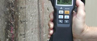
- Determination of concrete strength by ultrasonic method. In this case, a special ultrasonic installation is used, which “transparent” the structure being tested and determines the strength of concrete depending on the speed of propagation of ultrasonic waves.
- Destructive strength testing method. According to existing SNiPs, destructive control is mandatory when accepting a building or structure into operation.
- An independent method for determining the strength of concrete using available materials and tools: a hammer, chisel and calipers.
The listed methods have varying degrees of accuracy, which are within the permissible error.
DETERMINATION OF STRENGTH
Strength is the property of a material to resist destruction from external forces that cause internal stress. Under the influence of various external loads, materials in buildings and structures experience various internal stresses of compression, tension, bending, etc.
Strength is an important property for many building materials; its magnitude determines the load that a given element can bear for a given cross-section. If the material has greater strength, then the cross-sectional size of the building element can be reduced.
The strength of building materials is usually characterized by the ultimate strength in compression (Rcom), in bending (Rb) and in tension (Rp).
Table 1
Schemes of standard methods for determining strength
| Sample | Test scheme | Material | Sample sizes, cm |
| Compression test | |||
| Cube | Concrete Mortar Natural stone | 10x10x10 15x15x15 20x20x20 7.07x7.07x7.07 5x5x5 | |
| Cylinder | Concrete Natural stone | d=15, h=30 d=h=5;7;10;15 | |
| Tensile test | |||
| Rod, figure eight, prism | Metal Concrete(prism, figure eight( | l/d=10 l/d=5 5x5x50 10x10x80 | |
| Bend test | |||
| Prism | Cement Gypsum Brick Concrete Wood | 4x4x16 4x4x16 15x15x15 2x2x30 |
It is determined by testing material samples of the appropriate shape (Table 1) on hydraulic presses (Fig. 7), bending or tensile testing machines.
.
Rice. 7. Diagram of a hydraulic press for compression testing:
1 - bed; 2 - screw device for clamping the sample; 3 - upper support plate; 4 - test sample; 5 — lower support plate with a spherical surface; 6 - piston.
studopedia.ru>
Laboratory work No. 2 Determination of the tensile strength of concrete, wood and water resistance of materials
Goal of the work:
become familiar with the method of experimentally determining the compressive strength of a material and assessing its water resistance based on the softening coefficient.
As a result of performing laboratory work, the student must
know:
- basic structural characteristics and properties of building materials;
be able to:
- determine and calculate the compressive strength of a material and its water resistance based on the softening coefficient.
Materials:
- cube samples (at least 6 pieces) of hardened gypsum binder with an edge of 2...5 cm (the size of the samples depends on the maximum force developed by the press available in the laboratory).
Equipment:
- hydraulic press with a force meter or pressure gauge (maximum force developed by the press is 10...100 kN);
- porcelain or metal cup with water;
- yardstick.
Procedure for performing laboratory work:
1.
Strength
is the property of a material to resist destruction under the influence of internal stresses arising from external loads. Under the influence of various loads, materials in buildings and structures experience various internal stresses (compression, tension, bending, shear, etc.).
Strength is an important property of most building materials; the load that a given element can bear for a given cross-section depends on its value. If the material has great strength, then the cross-sectional size of the element can be reduced. The strength of building materials is characterized by compressive, bending and tensile strength. It is determined by testing samples (Fig. 1) in the laboratory on hydraulic presses or tensile testing machines.
2. Compressive strength
material is called the stress corresponding to the load at which destruction of the material sample occurs.
Ultimate compressive strength R
compressed, MPa, is determined by the formula:
R
сж =
р
/
S ,
where р
– breaking load, N;
| Fig 1. Samples for testing materials I - for compression; II-bending; III - tensile; A - dense natural stone; |
S
– cross-sectional area of the sample, mm2.
To determine the compressive strength, material samples are subjected to compressive external forces and brought to failure. The tested samples must be of the correct geometric shape (cube, parallelepiped, cylinder).
Samples from natural stone materials, shaped like cubes, can be of the following sizes: 50×50×50, 70×70×70, 100×100×100 mm. Samples from dense materials can be taken in smaller sizes, and from simple materials - larger.
Cubic-shaped samples are made using special circular saws. When sawing stone, abrasive powder mixed with a viscous suspension of heavy clay is introduced under the saw blade. For very hard rocks, such as quartzites, corundum, diamond and other discs are used. The stone sample is secured with the grips of the machine and sawed alternately in three directions.
The diameter of the sample cylinders can be 50 or 80 mm, and the height is no more than two diameters. Making cylindrical samples from stone materials (using special hollow drills) is much easier than cubic ones, since cube samples require careful processing of six faces.
Prepared samples - cubes or cylinders - are ground on a grinding machine along two opposite planes, which must be parallel. The correctness of the planes is checked with a metal square and a caliper. After production, the samples are numbered in black ink. Parallel lines indicate the direction of foliation. The shape and dimensions of samples of various building materials must comply with GOST requirements for each type of material.
| Fig 2. General view of the hydraulic press |
Hydraulic presses and universal testing machines are used to test material samples for compression.
Before testing, the sample is cleaned with a soft brush or cloth, weighed, and measured with an accuracy of 1 mm. and installed on the lower support plate of the press exactly in its center. The upper support plate is lowered onto the sample using a screw and secured tightly between the two support plates. Then, having made sure that the sample is installed correctly, the press pump is turned on and a load is applied to the sample, adjusting to the rate of its increase (0.5 - 1 MPa per 1 s.). At the moment of sample destruction, i.e. at the moment of the greatest load on the sample, the arrow will stop and go back. This moment must be recorded.
Each material is tested on at least three samples. The final result is taken as the arithmetic mean of the results of three or more samples. Test results, both individual and average, are recorded in the laboratory report.
3. The
bending strength
is determined on the same presses as the compressive strength, but special devices are used. Two rollers are attached to the lower support plate using two slats, which serve as a support for the test sample, and a bending knife is attached to the upper support plate using slats. Samples are prepared in accordance with GOST for the material being tested. For example, when testing cement, samples are made - beams measuring 40x40x160 mm, and when testing wood - beams measuring 20x20x300 mm are made. The load on the sample is transmitted by one or two weights.
Bending strength R
izg, MPa, determined by the formula -
- with one concentrated load and a sample - a beam of rectangular cross-section:
R
izg = (3
pl
) / (2
bh
2),
- with two equal loads located symmetrically to the axis of the beam:
R
izg = [
p
(
l - a
)] / (2
bh
2),
where p
– breaking load, N;
l
– span between supports, mm;
A
– distance between loads, mm;
b
and
h
– width and height of the cross section of the beam, mm.
The bending strength is calculated as the arithmetic mean of the test results of three samples.
4. Tensile strength
determined in such building materials as wood, building steels, plastics, and rolled roofing materials. Samples are usually made in the form of double-sided blades; the shape and size of the samples are determined according to the relevant GOST standards for the material being tested.
Before testing, the width and thickness of the sample are measured with an accuracy of 0.01 mm, after which the sample is secured in the clamps of the tensile testing machine. The sample is loaded evenly at the speed specified by GOST. The machine's force meter determines the maximum load. Tensile strength R
p, MPa, calculated by the formula:
R
p=
p / S
o,
where p
– breaking load, N;
S
o is the initial cross-sectional area of the sample, mm2.
The tensile strength is calculated as the arithmetic mean of the test results of three samples.
5. Sample testing:
Gypsum cube samples are numbered (the number is placed on the surface that was lateral during molding), the area of the numbered surface is measured and the obtained values are entered in the table. No. 3.
The samples are divided into two groups: No. 1, 2, 3 and No. 4, 5, 6. The samples of the first group are tested dry, the second are placed in water before testing for 10...15 minutes, depending on the size of the sample.
Dry and wet samples are placed in the press with the numbered (side) surface facing up. Lower the press plate to the surface of the sample and load the sample. The moment of destruction is determined by stopping and starting the reverse motion of the pointer of the force meter (pressure gauge) and visually by the appearance of cracks on the sample. Breaking force F
razr (or pressure gauge reading) is entered in the table. 3
Table No. 3.
StudFiles.ru>
Determination of concrete strength by non-destructive methods
- Determination of strength using a Fizdel hammer. When struck by the working part of a Fizdel hammer, an imprint in the form of a hole of a certain diameter is formed on the concrete surface, cleared of foreign materials. The diameter measured with a caliper characterizes the strength of concrete. To ensure reliable results, 12-15 blows are performed. To calculate the strength, the average diameter of the hole is taken.
- Determination of strength using a Kashkarov hammer. A blow from Kashkarov’s hammer leaves two imprints on the surface of the concrete. One imprint remains on the object under study, the second imprint remains on the standard (a concrete rod of known strength). Depending on the ratio of the diameters of the prints, the strength of the tested object is determined.
- The strength of concrete is determined by non-destructive methods using: a TsNIISK gun, a Schmidt hammer and a sclerometer. These methods are based on the principle of elastic rebound of the working body from the test object. The strength of concrete is assessed using the instrument scale on which the data obtained is recorded.
- Separation with chipping. For testing, a surface area in the body is selected that does not have a reinforcing belt. To test the strength, special anchor devices are used, embedded into the thickness of the concrete. The strength is assessed using the scale of the anchor device.
