Construction of a sewer well
Sewer wells are a mandatory attribute of external sewerage; without them, its installation is impossible. They must run along the entire length of the pipeline. Their design and quantity may vary slightly, depending on the type and purpose of the structure, complexity and length of the system.
The process of constructing such a device is not complicated, the main thing is to understand the difference in types of structures, because a homemade septic tank or cesspool is also a well, and to comply with the rules and requirements. After this, it will be easier to make an efficient and trouble-free sewage system for your home.
Why do wells need waterproofing?
Wells used in the sewerage system must be sealed. To fulfill this requirement, sewer wells are sealed or lined. When using reinforced concrete rings, it is necessary to waterproof the joints especially carefully.
Waterproofing of sewer wells is carried out using a special waterproofing compound, as well as mastic. The work is done like this:
- The surface is being prepared. It is necessary to remove dirt with a wire brush and dry the cameras.
- At the joints, a dovetail-type recess is made and a waterproofing compound is placed into it. Before applying the compound, it is recommended to slightly moisten the joints.
- After this, you can apply liquid mastic to the entire surface of the chamber. It must be applied in at least three layers.
- After applying each layer of mastic, you need to take a break from work for at least a day.
- It is important that during the formation of the waterproofing layer there is no mechanical impact on the chambers. In addition, waterproofing work must be carried out during the warm period of the year, since at subzero temperatures the mastic cannot fully dry out.
- To ensure uniform drying of the waterproofing layer, the surfaces of the chambers are covered with a special film. Or you can regularly moisten the waterproofing using a regular sprayer.
Sewage manhole lining is an installation inside a polyethylene “pipe” adjacent to the interior walls. In this way, a sewer well can be repaired if the audit reveals leaks. In addition, the height of the neckline can be increased.
Requirements
The requirements for sewer wells are regulated in SNiP 2.04.03-85. This act describes all aspects relating to these structures: location, classification, dimensions and characteristics. The document says that a well is installed if:
- there are turns or bends;
- pipe diameter or slope changes;
- pipeline branches occur.
Overall dimensions may vary. depending on the diameter of the pipeline:
| ∅ pipe (mm) | Dimensions (mm) |
| up to 150 | 700 |
| up to 600 | 1000 |
| up to 700 | 1250 |
| from 1000 | 1500 |
| from 1200 | 2000 |
The volume is not indicated, but knowing the depth and diameter you can calculate it yourself. The operational characteristics of concrete wells are reflected in GOST 8020-90, and plastic (polymer) wells in GOST 32972-2014.
Video: Sewerage made from concrete rings is the simplest and cheapest option
Also, when installing a well shaft, it is necessary to comply with sanitary standards, these include:
- cannot be installed near sources of drinking water and water supply systems;
- installation is carried out at a certain distance from residential buildings and neighboring areas;
- volumes must correspond to the number of users.
You can read more about sanitary standards in this article: Rules for installing a septic tank.
Advantages and relevance of sewage tanks
The installation of sewer wells is necessary in dense urban areas, as well as on the territory of a country house. The reservoir plays the role of a collector, inspection device, storage tank or other technical element that provides easy access to the underground pipeline.
Sewage well placement diagram
If there is a well, in the event of a failure of the water drainage system, there is no need to dig up and replace all the pipes - it is enough to carry out an inspection of the failed area. Therefore, the installation of sewer wells has undeniable relevance and justified advantages. The main advantages of using concrete structures include:
- ease of installation;
- high reliability;
- waterproof;
- resistance to aggressive environments;
- long service life.
Installation diagram of sewer wells made of concrete rings
Types of wells
To understand which and how many wells need to be installed on the site, you should understand their types. The sewer system may include the following types:
Each of them has its own specific function; sometimes they can be combined in one structure. Below we will take a closer look at each of them.
Lookout
A sewer inspection well can be installed on any system, regardless of its complexity. Helps monitor the performance of the sewer pipeline and is used for maintenance - cleaning, flushing, etc. Depending on the location they are divided into:
- linear - if the highway is long, it is located on straight sections, at a certain distance;
- rotary - installed in places where the direction of the pipeline changes;
- junction - mounted at the junction of several pipes into one;
- control - used at the junction of the local sewerage system with the centralized one.
Perepadny
Serves to change pipe laying depth or flow rate. They can also be used to bypass any obstacle. The design consists of a tank with inlet and outlet pipes located at different heights, and additional devices, for example, stages for reducing speed. Just like the previous view, they may differ slightly from each other:
- classic design - wastewater enters through the upper pipe and is discharged through the lower pipe;
- with baffle and drain walls - to change the flow rate;
- channels with a slope - to increase speed;
- structures with multi-stage drops.
Filtration
These models are used as a device for soil post-treatment of wastewater coming from a septic tank. The design feature of this well is the absence of a bottom and holes in the walls. Instead, a drainage layer of crushed stone or gravel is installed at the bottom and outside of the well.
Cumulative
A place for collecting and storing wastewater, in other words, an ordinary cesspool. When arranging it, it is important that the container is sealed and cleaned regularly.
How is installation carried out?
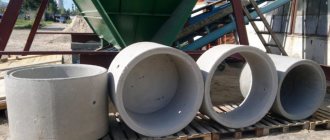
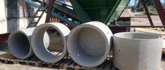
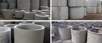
Let's look at how sewer wells are installed if reinforced concrete rings are used as the material. The volume of the rings is selected depending on the project.
- To build, you will need 2 or 3 concrete rings with a diameter of 1 meter and a height of 90 cm (these are standard sizes).
- A plate for constructing a bottom and a floor slab with a hole for installing a hatch.
Advice! Instead of a bottom plate, you can purchase a “blind” ring that has a bottom.
- A pit is being dug. Its diameter should be 50 cm larger than the ring size, and the depth is determined by the location of the supply pipe. The bottom of the pit should be 0.6 meters below the lower edge of the supply pipe.
- A sand and crushed stone cushion is made at the bottom of the pit. That is, a layer of a mixture of sand and small crushed stone 10 cm high is poured onto a well-compacted bottom. This layer should also be well compacted using a hand tamper.
- A bottom slab is laid on the cushion or the site is concreted (if a ring with a bottom is used, this operation is eliminated).
- Rings are installed in the pit. Since these products have significant weight, they are mounted using a manipulator crane.
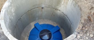
- The inlet and outlet pipes are connected, after which measures are taken to waterproof the connection points.
- The last thing to install is the cover with the hole for the hatch.
- If differential sewer wells are installed, their depth is determined by the magnitude of the relief difference. However, it is not recommended to make them deeper than three meters, since at a significant depth the cleaning procedure will be greatly complicated. The lowering is assembled from a cross, a pipe and an elbow. This design will make it easier to clear blockages; the lowering is secured with clamps. The drop is allowed to be carried out both inside and outside the well.
- It is recommended to backfill the pit around the chambers with clay. This material will provide additional waterproofing.
Material of manufacture
The sewer well shaft can be made of various materials. The most common:
- brick;
- concrete;
- plastic.
| Brickwork | High strength; if you know how to use a trowel, installation will not require much time. Holes in the walls are made during the construction phase. |
| Concrete | Installation - using formwork or installing ready-made rings. Holes for pipes in poured structures are made during pouring, in rings - with a hammer drill or other tool. |
| Plastic | Made from Eurocubes or barrels. There are also factory containers that include trays with various types of wiring. May require anchoring to concrete base. |
For brick and concrete wells, waterproofing of the walls, outside and inside, and the bottom is necessary.
Materials
Concrete well dimensions
At the end of the 19th and beginning of the 20th centuries. all wells were made of brick. In the mid-20th century, reinforced concrete began to be made, but now plastic structures are most often used. They can significantly reduce the cost of construction work and installation costs. However, in the countries of the former USSR this type has not found its application, since it is not resistant to low temperatures. Now a number of Russian manufacturers have begun the development and production of plastic wells for the cold zone.
Externally, the designs made from all types of material are absolutely identical. They have a shaft pipe, a cover, and sewerage entry points. In this case, holes for sewer pipelines are laid out in a brick well, in reinforced concrete ones they are drilled, and in plastic ones they are usually made in advance. Therefore, the construction of reinforced concrete and brick ones is much more expensive compared to plastic ones.
The covers of all wells are standardly equipped with storm water inlets, which allows storm drainage to be introduced into them. Hatches are usually made of cast iron and have their own load classes. The most common classes are “B” and “D”, which can withstand 12.5 and 40 tons, respectively.
You need to build a sewer system and a well using your own funds, because this determines what type of material will be used.
Installation of a concrete well
Sewage wells made of concrete and brick practically do not differ in the stages and progress of installation work. In any case, installation proceeds as follows:
- A pit of the required size is dug.
- The foundation is being laid - pouring the foundation or a finished slab.
- Construction of walls - pouring or installing rings.
- Waterproofing walls and seams.
- Backfilling and compaction.
- Cover device.
In order to lower the finished rings into the pit, you will need to use special equipment.
Installation of a plastic well
Ready-made containers made of plastic or other polymeric materials make it possible to complete all work without the involvement of lifting equipment and save time. The main thing is to choose the right location for the structure and its size. Installation is carried out in several stages:
- Digging and preparing a pit.
- The foundation is a cushion of sand and crushed stone or a poured base.
- Installation of the tank, if necessary, fastening to the foundation.
- Inclusion in the system.
To avoid filling a well of any type, it is recommended to make a concrete blind area around it along the entire perimeter of the neck, 1.5 m wide.
Video: Installation of a sewer well made of concrete rings
Plastic inspection wells
In a private country house, inspection wells are often required for preventive work on sewer and drainage systems. In a simple system where the slope, direction and diameter of the pipes do not change, they may not be needed.
In practice, plastic containers are widely used. It is advisable to choose them corrugated, since with seasonal temperature fluctuations the dimensions of the shafts change.
Finished products are expensive, so components can be assembled separately. To do this, you will need a plastic bottom, a pipe with a diameter of about 460 mm and rubber seals. If it is necessary to go down inside, the diameter is selected to be at least 925 mm.
Inspection well for sewerage: construction of a well in storm and wastewater systems
An extensive sewer network consisting of pipelines is located underground. I would like its important components to be accessible for maintenance, don’t I? For these purposes, you have decided to equip such an element of the system as a sewer inspection well, but you don’t know where to start?
We will try to help - this material discusses in detail the structure of this type of structure, important nuances that should be taken into account when assembling it yourself. There are also instructions for doing it yourself, in which step-by-step photos of the work process are selected for clarity.
To make it easier for a beginner in this business to understand the topic of constructing a well to control the sewer network, we have added videos on the installation of inspection wells from various materials.
Purpose of underground inspection chambers
The sewer circuit is designed for the prompt drainage of domestic wastewater, rain and melt water into specially designated settling tanks, sewer wells or collectors. Inspection wells are installed in the most critical sections of the sewer network.
For the equipment of a straight line 10 m long, the construction of an additional camera is irrational, while on a 100-meter section with intersection nodes, forced turns and level differences, control points are simply necessary.
Types of sewer wells
Varieties of inspection wells are distinguished based on two factors:
- main function and installation location;
- manufacturing material.
According to the first factor, there are linear, nodal, rotary and differential types. They apply equally to both domestic and industrial communication systems.
This means that any of the above types, if necessary, for example, due to the long length of the sewer pipeline, can be installed on your site.
Linear ones are installed on a straight pipeline. They are equipped with one pair of pipes or outlets, which are located opposite each other.
Such wells are necessary even if there are no prerequisites for an emergency, but the section is considered quite long (according to SNiP - from 35 m to 300 m).
Rotary types, as the name implies, are mounted on pipelines that turn to the side. The general rule applies: the angle of rotation should not exceed 90º, that is, it should not be sharp.
The pipes (holes) are not located on the same line, but in places depending on the angle of rotation, but at the same level in height.
Nodal models are installed at the intersections of two or more pipelines, as well as where the central line has branches.
Wells differ in design by the presence of additional pipes (holes). As a rule, all inputs/outputs are on the same level.
The differential pipes serve to increase or decrease the flow, so the pipes are located at different levels: the inlet pipe is usually higher, closer to the neck, the outlet pipe is at the bottom. The construction of differential wells is also used when it is necessary to reduce the speed of wastewater transportation.
Despite the functional and structural differences, all types of wells are very similar. They are made from various materials.
Initially, stone and brick were considered the best, but now there are practically no stone structures left. They were replaced by practical and easier to install concrete analogues.
Precast concrete factories produce standard parts, from which individual chambers are assembled during installation: simply install individual elements on top of each other, then seal the seams.
A modern analogue of concrete wells are polymer models, which are corrugated containers and are particularly durable and airtight.
Design
Manholes may be of a specific type, but, as a rule, they have similar design features. They contain the following elements: neck, tray, hatch, working chamber and base. They can be made from different materials, namely: plastic, reinforced concrete blocks, brick or stone. If the well is located in an area without a road surface, then the construction of a blind area around it is required; it is necessary for effective drainage of water. Inspection wells most often have a rectangular or circle shape in plan. The base is made of reinforced concrete slabs, which are mounted on a crushed stone cushion. In the design, the pipeline goes into a tray, which represents the main technological part. It is necessary for the movement of wastewater. Its total height should not be less than the diameter of the larger pipe. It is made of monolithic concrete using templates. Shelves are mounted on both sides of the tray, on which the working surfaces are located. These elements should have a slight slope directed towards the tray.
Location depending on destination
According to SNiP standards, there are points for mandatory installation of inspection cameras:
- in places of turns and slopes, when changing the direction of the linear pipeline;
- in places where additional branches are connected to the central line;
- in areas where pipe diameters are changed.
The entrances of private sewer networks to the central system (or collector) are also equipped with inspection cameras.
The diameter of the pipes directly depends on the length of the linear section. For example, a pipeline up to 35 m long consists of elements with a diameter of 150 mm, a hundred-meter section consists of pipes with a diameter of 700 to 900 mm, the maximum possible 300-meter line consists of pipes whose diameter can be more than 2 m.
The relationship is inverse, that is, if the diameter of the pipeline is 150 mm, then after 35 meters it is necessary to install a well.
The most difficult area is selected and an inspection camera is installed. Most often this is the place where an additional sleeve is inserted, for example, coming from a bathhouse.
Manholes for private use may differ from industrial analogues in size or number of pipes, but there is no fundamental difference.
Features of various types of designs
Requirements for reinforced concrete prefabricated structures are set out in regulatory documents GOST 2080-90 , which detail the technical requirements for products, give their characteristics, markings and provide links to related GOST articles.
The advantages of prefabricated structures over monolithic ones lie in the installation possibilities. Reinforced concrete parts are heavy, so they have to be transported and installed using special equipment. It is much more convenient to ensure the delivery of individual parts than the entire structure in finished form.
During installation, additional measures are sometimes required - for example, installing a waterproof lock. By assembling the structure in parts, it is much easier to carry out specific excavation work.
So, the lower part of the structure is a durable concrete slab, which is placed on a pre-prepared foundation. To give the structure stability and at the same time ensure the outflow of groundwater, crushed stone is poured into the pit before installation. The bottom slab is laid strictly horizontally on a crushed stone base.
The lower part is called the tray part; it is equipped with holes or pipes for installing the pipeline. The location of the inlet holes depends on the purpose of the well. Let's assume that in linear structures they are on opposite sides, in rotary ones - depending on the angle of rotation.
The main working chamber is larger in size than the others - it is into it that you should go down to check the shut-off valves, tightness of connections or wear of parts. For ease of descent, one wall is equipped with a ladder made of metal brackets.
The top of the working chamber is covered by a floor slab, to which another element is attached - the neck. It is narrower in diameter than the main part.
The neck is covered with a hatch, which performs two functions - it protects the well from the entry of unwanted guests and protects it from street debris and precipitation. To make it more difficult to get into the chamber, the hatch is made of heavy material - cast iron.
When installing inspection cameras in a suburban area, it is not necessary to use cast iron parts. Nowadays many types of polymer lids are produced that are more convenient and aesthetically attractive.
Requirements for the designs of polymer products are set out in GOST-R No. 0260760 . One of the common manufacturing materials is polyethylene. The reliability of the design is ensured by the production technology - the extrusion welding method.
The products are resistant to chemicals present in the soil and are wear-resistant, environmentally friendly and airtight.
Outwardly, they resemble large capsules with a hole in the neck. Unlike concrete analogues, plastic cameras are purchased and installed ready-made.
The products are adapted for quick installation and connection of pipes. Due to easy installation, many country home owners prefer plastic cameras.
Dimensions of concrete structures
A complete list of standard sizes can be found in regulatory documents, for example, in article 2.04.03-85 SNiP . Dimensions refer to the sizes of various parts of the structure and incoming pipes, as well as the distances between them.
If the diameter of the passing pipeline is 600 mm or less, the length and width of the concrete ring well must be 1 m.
As the diameter increases, the dimensions of the chamber increase:
- for rectangular reinforced concrete products – pipe D 700 mm = well D+400 mm;
- for round reinforced concrete products - pipe D 700 mm = well D 1250 mm, up to 1000 mm = 1500 mm, more than 1200 mm = 2000 mm.
There are types of wells that are not intended for drainage. If communications lie at a depth of 100-120 cm, and the diameter of the pipeline is 15 cm, a compact inspection chamber with a diameter of only 60 cm is suitable.
It is used for cleansing procedures. These products are often used in dachas for the installation of short-length storm drains.
Inspection sewer wells: purpose and design
Inspection wells are installed in the most important sections of the sewer pipeline. After all, with the help of these elements of the drainage system you can get close to the shut-off and control valves and the body of the pipe itself, laid to a depth of 1.5-2 meters.
That is, without a manhole, neither repair nor maintenance of the sewer network is possible. Therefore, in this article we will look at their structure, evaluate the typical types of wells and understand the installation diagram of this element of the drainage network.
Inspection sewer well
Sewer well: sizes and shapes
If the sewer pipeline has a diameter of up to 300 millimeters, then a round well up to one meter in diameter is more often used. In this case, the working chamber must be at least 0.7 meters.
For larger pipeline sizes, it is recommended to install a sewer well with a bottom diameter of at least one meter. In this case, it is better to choose a square bottom shape for greater convenience when installing pipes.
The angle between sewer pipes in the well should be no more than 90 degrees, with the exception of a device with a level difference.
Construction of a manhole
Any inspection well consists of the following elements:
- The reinforcing frame of the shaft (round or square section), into the inner part of which a ladder is mounted. Moreover, in the body of the frame there are special holes for the sewer pipes.
- Bottom - lower ceiling, smooth in shape or equipped with profiles for channels. In the latter case, the pipes or supply holes for pipelines are located directly at the base of the well (from the bottom end of the shaft).
- Top floor with a hole for a hatch.
- Hatch – round or square, with curtains or removable, equipped with a lock or regular. Moreover, on the outside of the hatch there is always a marking indicating the types of well (they will be discussed below in the text).
The typical material for the reinforcing frame, bottom and top floor is reinforced concrete. That is, the body of the well (the reinforcing frame of the shaft) is assembled from standard concrete rings. The bottom of the inspection well, in this case, is arranged using a round slab or by pouring mortar into the formwork laid at the base of the shaft. Well, the upper floor is equipped with the help of a pre-arranged slab with perforation for a hatch.
However, a modern sewer manhole can only be assembled from reinforced concrete. Heavy and short-lived concrete rings and slabs are being replaced by plastic parts. Moreover, polymer wells are assembled on the basis of two-layer polyethylene or polypropylene pipes (Corsis series and its analogues) with high ring rigidity. In this case, a special tray with branch pipes for mounting pipes end-to-end or in a socket is used as the bottom of the well. The role of the floor slab is played by a cast neck mounted on the upper section of the pipe.
Hatches for wells can be cast iron, steel, or polymer. Moreover, metal versions are more durable. Therefore, if the well is installed in an area with heavy traffic (on a road, highway, parking lot, etc.), then the hatch should only be metal (preferably cast iron).
Features of installation of the manhole hatch
An element such as a well hatch is an important element of the sewer system, despite its apparent simplicity. Its production is regulated by state standards; it is extremely important to buy a high-quality sewer manhole cover. For example, GOST 3634-61 states that the material for the hatch should be cast iron. Cast iron hatches consist of a body with one cover; they are designed for necks with a diameter of 70 centimeters. According to GOST, heavy hatches must have a mass of 134 kg, and light ones no more than 80. The difference is that light ones are mainly used on sidewalks, where they are subject to less load. In addition to cast iron, various polymer materials are used, which are lightweight and environmentally friendly.
Interesting fact: if hatches are made of polymers, then a special filler is added to them, which does not make them unsuitable for recycling.
This is done in order to resist vandalism, because the price of a sewer manhole for buyers will be zero.
Inspection sewer wells: overview of varieties
The classification of wells can be based on three characteristics, namely:
- According to the layout of pipes or holes for introducing sewer pipes.
- According to the functional purpose of the well.
- By type of pipeline.
According to the first classification method, there are the following types of structures:
- A linear well through which one branch of the pipeline passes. Therefore, the design of such a well provides one inlet or one outlet pipe (hole).
- A junction well, which is installed at the junction of two or more pipeline branches. That is, such a well has one inlet (or outlet) and several outlet (or inlet) pipes. And with the help of such a well, you can split the flow into several branches (or merge these branches into one stream).
- A differential well, which forms a slope in the sewer pipeline due to the displacement of the central axis of the outlet pipe (hole) relative to the axis of the inlet channel. In this case, the outlet pipe is located below the inlet pipe.
According to the second classification method, from the entire variety of designs, the following options can be distinguished:
- Rotary wells, inside of which there is an angular junction of pipeline branches. Therefore, the central axes of the nozzles of such wells are located at an angle to each other, and not along one line.
- Monitoring wells mounted above the revisions. Moreover, SNIP sewer inspection inspection wells are recommended to be located at every 30-300 (depending on the diameter) meters of the pipeline length.
- Filtration wells, in the internal space of which there is a differential or mechanical filter that cleans the flow from impurities.
- Storage wells or septic tanks (sand pits), with which you can partially clean the flow by separating solid waste from the liquid fraction. Such a well is installed in an easily accessible place. After all, it needs to be cleaned as silt deposits accumulate at the bottom.
The third classification method divides wells into the following types:
- Options for sewer networks, mounted on both domestic and main pipelines.
- Designs for stormwater networks. Moreover, the storm sewer inspection well involves servicing both surface lines and deep drainage pipelines (below the soil freezing level).
The structural differences between such wells are minimal.
Where are inspection wells installed?
It is customary to install inspection wells in the following places:
Inspection well at the branch of the pipeline branches
- At the corner junction of sewer or drainage pipeline branches. In this case, a rotary inspection well is used.
- At the branch of the pipeline branches. Nodal wells are installed here
- Along the entire length of the site, in increments of 30-300 meters. This is how control wells are installed.
- Where there is a difference in diameter or depth of pipes. In this place, differential, filtering or storage wells are installed.
As a result, even a novice designer of drainage or sewer systems can easily calculate the location of any inspection well. Well, when the location of the well is determined, you can begin installing the system.
DIFFERENCE WELLS
4.25. Drop wells should be provided:
to reduce the depth of pipelines;
to avoid exceeding the maximum permissible speed of movement of wastewater or a sudden change in this speed;
when crossing with underground structures;
with flooded outlets in the last well before the reservoir.
Note. On pipelines with a diameter of up to 600 mm, differences in height up to 0.5 m can be carried out without installing a differential well - by draining into an inspection well.
4.26. Differences in height up to 3 m on pipelines with a diameter of 600 mm or more should be taken in the form of weirs of a practical profile.
Differences in height up to 6 m on pipelines with a diameter of up to 500 mm inclusive. should be carried out in wells in the form of a riser with a cross-section not less than the cross-section of the supply pipeline.
In wells above the riser it is necessary to provide a receiving funnel, under the riser - a water pit with a metal plate at the base.
For risers with a diameter of up to 300 mm, it is allowed to install a guide bend instead of a water trough.
4.27. On rainwater sewer collectors, with a drop height of up to 1 m, it is allowed to provide spillway type drop wells, with a drop height of 1-3 m - a water trench type with one grate of water trough beams (slabs), with a drop height of 3-4 m - with two water trough grates.