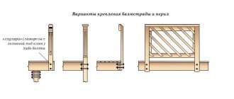
Design features of retaining walls
An uneven landscape is inconvenient to use, so most developers strive to level the soil throughout the entire site or create several zones with horizontal surfaces, between which you can move along steps or stairs.
The main problem is soil pressure on vertical walls, leading to negative consequences:
- loss of stability - overturning of the structure;
- loss of strength - destruction of individual elements and collapse of the slope.
Problems of operating retaining walls
Therefore, there are two fundamentally different technologies aimed at compensating for this pressure:
- massive walls - have a lot of weight, lateral movements of the soil cannot move the structure from its place;
Massive retaining wall
- thin-walled structures - the wall has elements that involve part of the soil in creating forces directed in the direction opposite to overturning.
Options for thin-walled retaining structures
In the first case, the consumption of concrete and reinforcement increases, in the second the volume of excavation work increases. The choice of technology for an individual developer depends on the available construction budget, free time, and the purpose of the retaining walls.
For example, with a limited budget, it is more advisable to install corner structures with a console. If the retaining wall is used for terracing, on the upper edges of massive monolithic multi-level walls you can lay out flower beds, make beds or use them in landscape design.
Series 3.002.1-2 issue 0, 1
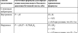
Scheme for determining pressures under the base of the wall a - at small eccentricities; b - at large eccentricities. The edge pressures of the soil under the base of the wall at the eccentricity of the application of the resultant of all vertical forces relative to the center of gravity of the base are determined by the formula. At large eccentricities, the pressure under the base of the wall (Fig. For a massive retaining wall, internal forces , and in the section of Fig.
Scheme for calculating the strength of sections of retaining walls a - massive; b - corner console type. For a cantilever-type corner retaining wall, bending moments in sections , and Fig. Transverse forces in sections , and are determined by the formulas:.
For rocky soils, the pressure under the base of the wall is calculated according to the instructions in paragraph. For an angle retaining wall with an anchor rod, the edge pressures of the soil and under the bottom of the wall are determined using the same formulas as for an angle retaining wall of a cantilever type. When determining the maximum forces in the elements of a retaining wall with an anchor rod, two cases of loading the collapse prism with a temporary load are considered: the load is located on the entire surface of the collapse prism (Fig.
Load diagram a—the load is located over the entire surface of the collapse prism; b - the load is located on part of the collapse prism. The maximum force in the anchor rod with a hinged connection of the front and foundation slabs is determined from the first case of loading according to the formula.
In formula 55, and are the distances of the points of application of the horizontal components of soil pressure to the base, and and are calculated for a soil height equal to.
Taking into account a possible increase in the force in the anchor rod due to the hovering of the soil above it and uneven tension, an additional operating condition coefficient of 1.5 is introduced to the calculated axial force in the rod. The indicated increase in thrust force is taken into account when calculating rods, their fastenings and embedded elements and is not taken into account when calculating reinforced concrete sections. Vertical and horizontal reactions at the junction of the anchor rod with the elements of the retaining wall are determined by the formulas:.
The force in the anchor rod with a rigid interface between the front and foundation slabs is determined by the formula. Calculation scheme for determining the horizontal reaction with a rigid junction of the front and foundation slabs. Bending moments and shear forces in sections and walls with anchor rods are determined by the formulas:. Scheme for calculating the strength of sections of corner retaining walls with anchor rods. Taking into account the possible increase in force in the cantilever part of the vertical wall element due to its flexibility and redistribution of soil pressure, to the design moment obtained by formula 58 for the cantilever part 0; 0, an additional operating condition coefficient of 1.5 is introduced.
The specified increase in force is taken into account only when calculating the strength of sections of the cantilever part of the front slab and does not apply to other areas. Calculation of the slotted groove in the case of rigid coupling of the prefabricated face slab with the foundation slab, Fig. The shear force is applied to the top of the groove wall. In the upper and lower parts of the groove wall, compressive stresses arise with the height of the compressed zone and. Scheme for calculating a slotted groove.
Decorative walls
Before making a concrete retaining wall with a height of 30–70 cm, you need to take into account the following nuances:
- for low structures, the best option is a massive wall (trapezoid or parallelepiped with a wide base);
- they have significant weight, so heaving forces are not able to move them;
- with a structure height of up to 0.3 m, a foundation is not needed, but the fertile layer must be replaced with non-metallic material with your own hands to a depth of 0.4 m;
- if the planned height of the terrace is 0.4 - 0.8 m, the lower part of the wall, which is the foundation, is deepened by 0.15 - 0.3 m.
Low retaining wall
The technologies for their manufacture are discussed below; this section provides only design rules. In low substations, drainage is not necessary on dry soils; in case of high groundwater level, perforated and geotextile-wrapped corrugated pipes are laid on the inside with a slope towards the underground reservoir for collecting wastewater.
Why are retaining walls needed on a site with a slope, types of retaining walls
Retaining walls are installed in areas with level differences at the boundaries of platforms and steps in order to:
• Formation and strengthening of smooth horizontal terraces and ledges.
• Eliminate the risk of soil slipping and collapse.
• Creating optimal conditions for planting and preventing soil washout.
• Zoning and decoration of the site.
The functions of the walls are largely determined by their height. As a rule, compact walls up to 50 cm high are intended for zoning and decoration, medium ones (50-70 cm) are quite reliable supports, and structures from 1 m and higher are used as full-fledged barriers holding a large mass of soil. In this case, walls with a height of more than 1.5 m are classified as permanent buildings and require parameters to be justified by calculation.
Depending on the material and manufacturing method, there are:
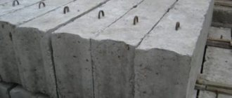
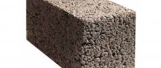
• Prefabricated walls made from large wild stones and building blocks, including cinder block, brick or reinforced concrete.
• Monolithic retaining structures, poured directly on site from concrete.
• Prefabricated, precast-monolithic and monolithic thin-walled structures from ready-made reinforced concrete slabs, reinforced with soil or carbon fiber anchors.
• Walls made of logs or thick boards, impregnated with machine oil or similar hydrophobic compounds that extend the life of the wood with constant contact with the ground.
• Walls made of gabions filled with rubble, pebbles or other types of decorative stone.
• Reinforced soil retaining walls laid using geogrids or geotextiles.
Almost all of the listed varieties have a common design scheme, including the base, the parapet itself and drainage elements.
a separate foundation and special preparation of the site; its depth depends on the looseness of the soil and varies from 1:2 to 1:4 in relation to the outer part.
The partition has a slight slope (5-10°) and is maximally protected from direct contact with soil and moisture on the inside, and atmospheric and mechanical influences on the outside.
Middle walls
Typically, suburban areas in cottage villages have height differences of within 1 m, but for garden plots, the administration of settlements often allocates land unsuitable for agriculture, replete with mountains and ravines. Therefore, PSs with an average height of 0.8 - 1.5 m are used, which also cannot be counted on to shear and destruction.
The scheme for selecting a substation design that satisfies operational requirements is as follows:
- at a height of within 1 m on loose soils, massive structures with a widened heel can be used;
- if the height difference is greater than the specified value, a thin-walled substation of any type will cost less.
The middle retaining wall
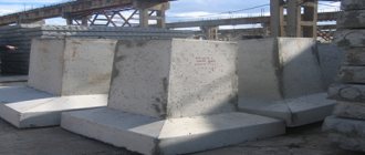
If in industrial and agricultural construction reinforced concrete panels and slabs are more often used for these purposes, then for an individual developer they are unnecessarily expensive, taking into account delivery, unloading and installation with special equipment. Therefore, it is easier to fill them locally using the technology below.
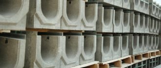
Drainage for substations of medium height is mandatory; instead of longitudinal drains, transverse drains are usually used:
- polymer pipes are laid just above the base of the foundation, passing through both vertical (inclined) formwork panels;
- step of transverse drains within 1 m;
- Stormwater gutters are placed at the junction of the substation and the lower terrace to collect and drain these runoff, which will inevitably destroy the soil and reduce the quality of operation of the site.
Perforation inside the drains is not necessary; sewer (only red) polyethylene pipes of suitable diameter can be used.
Photo
The site for building a garage is not always perfectly level. If the construction site is located on an inclined surface (angle of inclination more than 80), then for the safety of the erected structure, care should be taken to additionally “preserve” the moving soil. For this purpose, retaining walls are used to prevent collapses and landslides of the earth on the slope. They play the role of reliable “shields” that balance the balance of forces in places where the terrain of the site varies. Supports are installed along the entire earthen “step”, completely edging its depressions and protrusions.
With the advent of new building materials, the design of retaining walls has changed significantly. Now, with the help of protective “bastions”, a site with a difficult “character” can not only be strengthened, but also decorated. It is not for nothing that a decorative retaining wall is one of the popular techniques in landscape design, which allows you to effectively delimit zones of a site and place a certain emphasis on one of them.
High walls
Complex terrain may require high (1.5 - 2 m) retaining walls, which require calculation using two limit states. General design principles are:
- the use of thin-walled structures, since massive PSs are not economically feasible here
- elements involving the soil of the upper tier to create forces directed against overturning (cantilever, anchor or buttress) are selected depending on the preferences of the developer.
High retaining wall with buttresses
The volume of excavation work is approximately the same, but additional concreting will be required for buttresses and consoles.
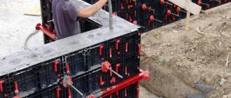
Formwork of monolithic walls
Formwork is something without which it is impossible to form monolithic structures, both concrete and reinforced concrete. These structures, depending on their disassembly, are divided into 2 types:
- removable wall formwork;
- permanent formwork.
The most common formworks are removable, in a variety of variations. The name “removable” suggests that the panels or boards from which the wall formwork is made are removed after the concrete has completely dried or initially set. Removable formwork is used not only to form the foundation - it is a full-fledged participant in the construction of monolithic walls and frames of multi-story buildings, with its help flights of stairs and decorative elements are made.
Removable formwork for monolithic construction
What is used to make removable formwork:
- wood (boards, boards, etc.);
- plywood;
- steel sheet;
- aluminum (both sheet and form);
- polyvinyl chloride;
- various combinations of the above materials.
Regardless of the formwork material, there are a number of requirements that are the same for all:
- The frame must have sufficient rigidity and be fixed in place.
- The gaps between structural elements should be minimal, for which they need to be carefully adjusted. Cement laitance may leak through the gaps, causing the quality of the finished concrete product to suffer.
Example of permanent formwork
Permanent wall formwork is a structure that, after pouring concrete and hardening, remains in the concrete mass as part of the overall structure. The materials used for its manufacture must be:
- thermal insulation;
- durable (when pouring concrete, significant pressure is generated on the formwork structure);
- with low thermal conductivity (a monolithic concrete structure has high thermal conductivity, so concrete and formwork must form a single thermal insulation pair).
Related article: How to lay mosaic tiles on a wall
When using permanent formwork, concrete is more reliably protected than in a removable structure from various adverse external factors, primarily from moisture and extreme temperatures. This is a kind of multilayer sandwich made of formwork and concrete, where concrete provides strength and formwork provides thermal insulation. In this case, a calculation diagram must be made indicating the proportions of the mixture.
The principle of formwork
Permanent wall formwork can also be constructed from cladding panels, which is very beneficial for achieving an aesthetic result. In private house construction, thermal insulation materials such as polystyrene foam and wood concrete (a material made from a mixture of wood industry waste with a cement solution followed by the formation of hollow blocks) are very interesting for use as formwork.
Massive retaining wall
Below are drawings of massive walls for terracing the site. The general rules for constructing these structures with your own hands are:
- the formwork is buried 1/3 of the height of the substation structure with a total height of 0.4 - 1.5 m;
- if the wall has a height of 1.6 - 2 m, the minimum depth is 0.7 m;
- the minimum thickness (for trapezoidal ones in the upper part) of the PS is 10 cm;
- when terracing sandy soils and sandy loams, the width of the base is 0.5 of the height of the structure, for loam 1/3 of this size is enough, for clay ¼;
Dimensions of a retaining wall depending on the type of soil
Despite the fact that straight contours are preferable for landscape design, a properly designed terrace wall with your own hands should have stiffeners, corners and broken lines that provide greater strength to a monolithic structure made of reinforced concrete.
With heel widening
The technology allows you to reduce the construction budget due to less concrete consumption. Walls for terracing the area are being constructed according to the following scheme:
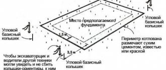
- marking and excavation - in accordance with the project, cords/strings are pulled over the cast-offs, trenches are made with a width equal to the size of the widening of the sole of the PS;
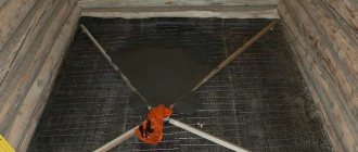
- underlying layer and formwork arrangement - the lower 0.4 m of heaving soil is replaced with crushed stone or sand, compacted, roofing material is spread on non-metallic material and formwork panels are installed for widening with a height of 0.3 m, pieces of timber are laid perpendicularly on them, on which panel formwork is installed for wall body, fixed on both sides with jibs and ties;
- drainage - the panels are drilled through, plastic tubes are passed through them at intervals of 1 m at a height of 0.2 m from the lower terrace;
- reinforcement and pouring - a frame with two belts of longitudinal rods tied with clamps or vertical and horizontal jumpers is installed inside the formwork with your own hands, the concrete is laid in layers (0.4 m), compacted with an in-depth vibrator.
Retaining wall with widened base
Concrete grade from M150, if necessary, penetrating additives can be used. The PS design has a slab part that resists heaving forces, preventing the wall from being pulled to the surface.
Trapezoidal
The manufacturing technology looks like:
- marking - cords are pulled along the cast-offs, taking into account changes in the horizontal level in the lower section and the upper tier adjacent to it;
- trench separation - the soil is removed 0.4 m below the design level, the width of the excavation is equal to the size of the widening of the base, taking into account the type of soil (for example, if the wall has a height of 0.7 m at the top, on loam it will be 0.23 m);
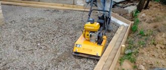
- underlying layer - sand on dry soil or crushed stone with a high groundwater level 0.4 m thick (layer-by-layer compaction with a vibrating plate or hand tools);
- formwork arrangement - the front panel is installed vertically (towards the slope), fixed with supports, the rear panel is tilted towards it with the top side, secured with pins or spacers made of timber;
- reinforcement - a frame made of longitudinal rods (corrugated with a diameter of 6 - 8 mm), tied with clamps every 0.6 - 0.8 m;
- concreting - the mixture is laid in layers of 0.4 m, compacted with a vibrator.
A curved path of the wall is preferable to straight lines.
Concrete care is classic - the upper plane is covered with sawdust, moistened from a watering can in the first two days. Penetrating additives introduced into the mixture during production make it possible to obtain absolutely waterproof concrete. However, its cost increases several times, so it is easier to use the technology:
- waterproofing of rear and side edges;
- facing the front surface with paint, stone, flexible tiles and other materials.
Backfilling is possible after concrete has gained strength; stripping for waterproofing takes 7–28 days, depending on temperature and air humidity. Drainage is similar to the previous case.
Calculation for a retaining wall
A more detailed dive into the topic reveals that there are standards, tolerances and restrictions. And the most important thing is the methods and calculations. Literature where you can get information:
- This is primarily SNiP - a whole section is devoted to the regulation of retaining walls.
- It is supplemented by the Reference Manual for SNiP - this is more detailed information on which designers are guided, the basis for programs and calculators. It's called "Design of Retaining Walls and Basements."
- The information is well presented in the “Technical Guidelines for the Design of Retaining Walls for Transport Construction” and the textbook “Calculation of Retaining Walls” by Klein for 1964.
Everything else is sites on landscape design - for starting independent construction, this is superficial, often contradictory information. It mainly concerns decorating the relief and “playing up” minor differences in height - more about the design of retaining walls.
Choosing the optimal type of supporting wall
In general, to organize the strengthening of differences in the height of the terrain, various types of supporting walls are used and they are arranged in fundamentally different ways:
- Pile method.
- Massive walls - reinforced, unreinforced.
- Corner console.
However, special equipment is required to install concrete piles and sheet pilings. We need a retaining wall design to make with our own hands.
Reinforced concrete structures are of course “more graceful” than massive ones, thinner - their cross-section is similar to an angle. A superficial inspection gives the impression that production will require significantly lower costs. With an increased degree of mechanization this is true. But for your own production the situation is somewhat different:
- They require more voluminous calculations - it is necessary to very accurately calculate the possibilities of saving concrete due to reinforcement. If you put a large margin of safety in concrete, the meaning of its use is lost.
- In addition, the requirements for the quality of work are greatly increased - mandatory control of the protective layer, careful bayoneting or vibration.
- As a result, we receive increased requirements for the construction of formwork.
This is only what is “on the surface”; the construction of retaining walls only seems simple in appearance. Failure to comply with even one of these requirements is critical, and it is also not always possible to do independently. That's why we chose a massive wall.
Some SNiP requirements
To carry out such work, in addition to economic feasibility, the most important condition is strength. Therefore, the basis of the calculation is the requirements of construction norms and rules. They regulate certain minimum parameters of retaining walls and the position of elements:
- The minimum permissible depth for laying the base - the so-called sole - is 60 cm.
- To begin calculations, its width is assumed to be within 0.5 – 0.7 of the total height of the entire wall.
- The slope of the lower plane of the base - deepening towards the “mountain” - 12.5 cm per linear meter (promotes the resistance of the wall to shear).
- Any smallest size of width, thickness for the cross section of a “massive” concrete structure, for example, the top cut - no thinner than 40 cm.
In addition, the drainage structure is regulated - there are 3 types: longitudinal, transverse and combined.
Initial data
Let's start with the fact that the task is to install a retaining wall, the average height of the soil level difference is 130 cm. For such conditions, based on the minimum depth of the foundation, the recommended total height of the wall is 2 m (above-ground and underground parts together). This way the main overall dimensions were determined.
It should be noted right away that independent calculation of a retaining wall is carried out using the selection method - optimal dimensions are taken and the parameters of the wall are calculated. If the stability condition is not met, the required dimensions are increased and a new calculation is carried out. If the stability margin is too large, the dimensions are reduced and everything is re-shielded again. It is clear that stability is affected by the dimensions of the base of the wall.
The overall dimensions of the retaining wall and the costs of their creation, in order to optimize costs, were calculated separately for both reinforced concrete and concrete - a massive structure without reinforcement. Their resistance to shear and change of position is the same. Each type of wall requires a different amount of excavation work. Although in fairness it should be noted that if the exact, specific position of the wall is not limited by anything, then at the initial stage the cost of excavation work can be reduced by choosing a little less soil. In this option, additional bedding is assumed after the work.
In addition, the economic costs for the construction of 1 linear meter of wall were calculated.
It is obvious that in a particular case, a massive concrete retaining wall is not only much easier to manufacture, but also cheaper. This is especially noticeable when the entire structure is long.
However, nothing has ever been mentioned about soils, or more precisely about their properties and parameters. A retaining wall is being erected at the dacha, where engineering and geodetic surveys were carried out earlier, during the construction of the foundation of the house. Of course, not specifically in this place, but at a slight distance the main part of the soil is loam. Therefore, guided by the reference table of the SNiP manual, we find the characteristics for the corresponding type of soil.
Standard and calculated soil indicators
Next, using the formulas from the same manual, the specified standard values must be recalculated to suit your soil. Obtain values for limit states - that is, taking into account safety factors:
To increase the accuracy of the calculation, the side of the wall, which will subsequently serve as a support for the soil, is conditionally divided into 2 planes:
- The supporting plane of the wall body is vertical; this position is convenient for proper installation and control of the position of the formwork.
- The lateral plane of the base is inclined, this is planned to prevent spontaneous soil shedding during work.
For the main supporting plane, we calculate the coefficient of direct soil pressure on the retaining wall in the horizontal direction. Next, the slope angle for the sliding surface takes into account the opposing friction, which reduces the active action of the soil on the wall and, as a result, increases its stability.
To update calculations in regions with different seismicity, the coefficient of horizontal soil pressure is taken into account. And the intensity of the influence of horizontal active soil pressure in the lower part of the supporting wall is calculated - where the concrete wall is installed on the foundation.
The main supporting plane of the wall body takes on the main loads. The supporting plane of the base of the wall is much smaller in area, but its depth certainly also matters. It cannot be excluded from the calculations, so we calculate everything the same way as we did for the main supporting plane of the wall.
Based on the results of the calculations, we can clearly display the effect of depth on the force of horizontal soil pressure:
- The red component of the graph is the dependence for the main reference plane of the wall. Moreover, a fairly significant part of it is in the negative range of values. Of course, there is no reverse effect - the soil is not able to “pull” the wall behind it. This is due to the properties of the specific soil – loam. The depth of occurrence affects its stable state through its own cohesive forces. Naturally, for any other soil the dependence will be different.
- The blue part of the graph is an illustration of the influence on an even deeper part of the wall - its base.
The process of previous calculations may seem somewhat vague, and the motivation unclear, but they are necessary to calculate a more understandable value - the shear force acting on the retaining wall, depending on the mass of the soil.
To simplify the calculations at least to some extent, it is conventionally assumed that there is no additional load on the ground from above. That is, the shear force of only the weight of the soil itself is calculated. The result is 21.69 kN. it turns out that a pressure of 2.1 tons is applied to 1 linear meter of a wall with a height of 1.3 m .
Having calculated the shear force, you next need to obtain the value of the force holding the retaining wall. And understand the relevance of the wall parameters, their compliance and sufficiency for its stability. One of the fundamental parameters is the mass of the wall. To do this, you need to calculate the cross-sectional area of the retaining wall (breaking its drawing into simple geometric shapes, the calculation of the area of which is elementary), and multiply by the average density for heavy concrete - 2300 kg/m³. We get the mass of one linear meter of the retaining wall.
Next, we calculate the holding force. It is created by the passive resistance of the soil, because the foundation is buried in the soil according to the SNiP standard by at least 60 cm, which means that it is to some extent restrained from shifting.
It is necessary to obtain a complex value - the total, total holding force of the retaining wall, for comparison with the obtained value of the shear force, taking into account safety factors.
As they say, the moment of truth has come. Calculations have shown that the forces promoting the shift of the wall are less than the forces holding it. This means the wall is stable - not subject to shifting. Which should be an indispensable result, otherwise there is no point in starting construction according to these parameters - you need to again select more suitable dimensions for the foundation.
However, SNiP and the design manual also require further calculations:
- A calculation is carried out of the possible change in the position of the wall - shifts caused by other reasons, we are talking about tilting, collapsing, prerequisites for capsizing. But in this case, passive soil pressure increases, contributing to the stability of the wall.
- The strength of the structure is calculated. In our specific example, the safety margin turned out to be quite significant, even creating the general impression that the structure could be “lightened” to some extent.
Looking further, there is a great temptation to carry out a full calculation for a reinforced concrete structure. But we initially rejected it due to increased requirements for quality of execution. This does not mean that a “negligent” attitude towards work is planned in advance. Just a small accidental inaccuracy, for example, in the position of the reinforcement, will contribute to the beginning of irreversible destruction of the retaining wall.
Summing up the results of the calculation, we note that under our conditions and the accepted overall dimensions: the height of the retaining wall is up to 2 m, and the width of the base is at least half the wall - if the other regulated parameters are observed, it passes in terms of strength.
The upper part of the wall is at least 40 cm, while it thickens towards the base with a slope of 3:1 (3 parts of height per 1 part horizontally) - the element also corresponds to the required strength.
What can affect the stability of retaining walls?
The most important characteristics that concrete supporting walls must have are stability and tolerance of high loads from soil pressure. This is a guarantee that the structure will not be destroyed as a result of soil collapse.
The supporting structure may be influenced by the following factors:
- The level of vibration that occurs when the land plot is located in close proximity to a highway with heavy traffic flow or near a railway;
- Seismic phenomena of various types during construction in seismically active regions;
- The level of groundwater passage and its activity during rainy periods, as well as flood phenomena in the region;
- Level of soil swelling during winter months.
A concrete retaining wall will be stable if its thickness is selected correctly, which depends on the height of the structure and soil characteristics. When constructing a wall on soft ground, it is recommended to increase its width.
Important! When constructing a retaining wall over 2 meters in height, it is necessary to take into account the wind loads of the specific construction region.
Wall construction
Regardless of the material, the retaining wall device has three main elements:
- Foundation. It is this part that ensures the stability of the wall and takes on the entire load.
- Wall body. This part is above the ground and prevents ground collapse.
- Drainage. This element is necessary to drain water from the retaining wall, which increases the service life of the structure.
Despite the apparent simplicity of the structure, not everything is so simple. It is necessary to take into account many factors and carefully select the material so that the structure will last for many years.
Gabion retaining structures
Not long ago they began to construct retaining walls from gabions. But this type has already gained popularity due to its simplicity.
Gabions are a frame made of galvanized metal, which is filled with stones. This type has many advantages:
- ease of installation and minimum time;
- Possibility of installation at any time of the year;
- mobility (can be easily disassembled and assembled in another place if desired);
- additional stability due to its own weight;
- greater flexibility, which allows you to withstand local loads;
- natural drainage system - holes between stones.
For greater stability, each gabion is connected to its neighbors using wire.
Brick and gabion walls
Bricks and gabions can become the materials that form the basis of the wall. Compared to masonry, the base should be 30 cm wider. The trench is deepened by the same amount. In soft and loose soil, the depth of the base in relation to the height of the wall should be 1/2. To mix the solution when pouring the foundation, you should use: gravel, crushed stone, concrete.
Note! The construction technology at the first stage does not make much difference. And the work is carried out according to the same algorithm as in the case when the structure is made of concrete or FBS blocks.
Features of building a brick wall
In the place where the wall is provided, you should dig a trench, at the bottom of which a gravel-sand cushion is laid. The walls are covered with formwork, into which a mortar with reinforcement is poured. After waterproofing work, you can begin building a brick wall. Pegs are driven in on both sides and a rope is pulled between them. Masonry is carried out according to the same principle as in the case of ordinary walls. Cement mortar is used to fasten the products together. To mix it, part of the cement is combined with three parts of fine sand.
Construction of a gabion wall
Such walls may have a reinforcing panel or have a massive structure. The last option is the most common. Gabions do not exceed 8 m in height. If this value should be higher, a berm should be installed. It is a section of slope of impressive width.
Gabions are placed with a bandage. The vertical seams are shifted in the upper rows relative to the lower ones by 25 cm. If the wall is not high, it can be installed on compacted soil. The soil surface is calculated and leveled before starting work. If the height is more than a meter, a foundation will be required. It can be made from flat gabions, which are located on a bed of sand and gravel.
The advantage of gabions is that over time such a wall becomes stronger, because plants grow through the stones. Installation work consists of installing containers at the site of operation and filling one third with stones. The correct installation is then checked relative to the horizontal and vertical. Once you are sure that there are no distortions, the gabion can be filled to the full. For filling you can use:
- soft limestone;
- granite;
- basalt;
- erclez;
- sandstone;
- dense limestone.
In order for the structure to last up to 20 years, you should choose a mesh with a zinc-polymer coating, which will prevent corrosion. If the soil allows, you can do without a foundation, but when purchasing gabions you should stock up on flat meshes that have a small height. The latter value can reach a maximum of 50 cm.
Installation is carried out on a flat surface, which is covered with geotextiles. The elements are fastened to each other using galvanized wire, this ensures the stability of the structure. If the retaining wall is to be installed near bodies of water or coastlines, cylindrical gabions should be used, but their filling remains the same.
Such designs are good not only for their strength and stability, but also for their flexibility. They may be installed in damp environments and the soil may be unstable during use. Walls, perhaps, look the most attractive of all the others, and their installation takes less time. The period of year for installation work does not matter, nor does the presence of a foundation. And if the soil moves, the structure will adapt to such conditions. In this case, no deformation occurs, as well as destruction of the wall itself.