- All about types of LEDs
- Main three types of LEDs
- Basic parameters of LEDs in LED lamps, strips, lamps
- Types of SMD LEDs and their features
- Rating of SMD LEDs
- How to correctly decipher the marking?
- Advantages and disadvantages of LEDs
Output LEDs SMD LEDs COB LEDs
Current Voltage Power Luminous flux Color temperature Dimensions
Single-, double-, triple-chip SMD LEDs Glow color Standard size
How to identify an LED by appearance? How to determine the polarity of an LED?
This article reveals the secrets of LEDs that are known only to specialized specialists. You will learn what types of LEDs are produced by industry, get acquainted with their manufacturing technologies and characteristics. A separate section is devoted to the features of the model range of LEDs used in ice strips and lamps.
We will tell you how to recognize the markings of light-emitting diodes, how to find out the parameters of an LED, and determine the location of the anode/cathode based on subtle signs. You will see that a regular ruler will help you find out the size of the SMD diode and then find the necessary information about it.
All about types of LEDs
At first, LEDs were used only as indicators on hardware and equipment. The brightness of the indicator light-emitting diodes was low, and their glow was clearly visible only in the dark. The products differed in their lead design - two leads (anode and cathode) came out of the round body.
With the development of technology and the emergence of the need for alternative light sources, more powerful and brighter diodes have appeared. The result of many years of development are SMD diodes and multi-chip COB diodes. They are used in modern LED lamps, chandeliers and spotlights, differing favorably from incandescent and halogen lamps in their greater light output and brightness, reaching several thousand lumens.
Main three types of LEDs
Let us consider in more detail the main types of light-emitting diodes, which have different designs and are produced using different technologies.
Output LEDs
Output LEDs are characterized by the presence of so-called “legs” intended for mounting them in the holes of the printed circuit board. This type of product is used for display and illumination.
Some modifications are used in household flashlights, portable ice lamps, and “laser” pointers. There are 3 standard modifications of housings:
Round 3, 5, 8 mm
Rectangular LEDs "Piranha"
Cylindrical LEDs
SMD LEDs
SMD LEDs are installed on the board using the surface mount method. Their basis is an LED chip (crystal) housed in a rectangular or square housing. The positive and negative terminals are made in the form of metal strips.
The process of creating an SMD diode consists of four stages: crystal growth, planar film processing, binning (sorting chips into categories - bins), placing the resulting chips in a specialized package. The crystals are grown using technology using metal-organic epitaxy: layer-by-layer growth of the crystal structure and the creation of contact taps from each pn junction.
The grown crystals are placed on a substrate that removes excess heat. With effective heat dissipation, even powerful models operate in a stable operating mode. The trouble-free service life is several years.
One of the optical coating options, most often a phosphor, is applied to the surface of the finished chips. A plastic focusing lens is mounted on powerful light-emitting diodes, forming the directional pattern of the light flux.
LED lamps are equipped with an assembly of SMD diodes, which provides the required amount of light radiation, measured in lumens.
COB LEDs
The idea of a COB matrix is to place a large number of LED elements on a common substrate. This solution provides a higher density of crystals per unit area compared to SMD technology (discrete chips in separate packages).
As a result, the compact matrix emits a total luminous flux with better intensity and uniformity. A ceramic or aluminum substrate with diodes is hermetically filled with phosphor. To remove excess heat, the finished board is installed on a radiator.
COB diodes are connected in series in clusters. With a power supply of 9 volts - 3 pieces, 12 volts - 4 pieces. The operating current is normalized based on the type of crystals used. The connection of the created cluster chains is done in parallel according to the required output power/brightness.
Flashing LEDs: purpose, description
You can often find flashing LEDs on the shelves of stores selling radio components. They vary in strength and color of glow. Flashing LEDs (MSDs) are semiconductor elements with built-in integrated pulse generators, the flash frequency of which is 1.5-3 Hz.
Many radio amateurs believe that these devices are useless and should be replaced with cheaper indicator LEDs. Perhaps they are right in some ways. However, MSDs also have a right to exist. Let's try to figure out what the advantages of such products are.
Flashing LEDs, in fact, are complete functional devices, the main purpose of which is to attract attention, that is, the light signaling function. It is also worth noting that the flashing semiconductor elements do not differ in size from standard indicator LEDs. However, despite its compact size, the MSD includes semiconductor chip generators, as well as some additional elements. If we construct a pulse generator using conventional radio components, then this design would have quite substantial dimensions. It's worth noting that flashing LEDs are quite versatile. The supply voltage of such elements lies in the range of 1.8-5 V for low-voltage devices and 3-14 V for high-voltage ones. The photo below shows a flashing 12 volt LED.
Advantages of MSD:
— wide range of supply voltage (up to 14 volts);
— small overall dimensions;
— a fairly compact light signaling device;
- different colors of radiation. Some flashing LED options have multiple built-in color diodes with different flash rates (the photo shows a flashing yellow LED);
— the use of MSDs is justified in small devices that have strict requirements for the size of the element base and power consumption. These diodes, thanks to their electronic circuit assembled on MOS structures, have low current consumption with a sufficiently high glow power;
— a flashing semiconductor device can even replace a functional unit.
In the circuit diagrams, the graphical representation of the MSD differs from a conventional LED only in the dotted arrow lines, which symbolizes the blinking properties of the element.
Let's take a closer look at the design of flashing LEDs. Through the transparent body of the element you can see that the diode consists of two parts. The light-emitting crystal is located at the base of the cathode (negative) electrode, and the chip generator is located at the base of the anode (positive electrode). All parts of this device are connected by three gold jumpers. The chip generator is a high-frequency master oscillator that operates constantly, its frequency fluctuates around 100 kHz. Also on the flashing diode circuit there is a divider assembled on logical elements. It divides the high frequency value to the level of 1.5-3 Hz. You may ask: “What is a high-frequency generator with a divider used for? Why couldn’t a low-frequency generator be used, and thereby simplify the design?” This is due to the fact that to implement a low-frequency oscillator, a large capacitor for the timing circuit is required. To implement such a capacitor would require a much larger area than for using a high-frequency generator.
So we looked at what a flashing LED is. And to the question of what is better - MSD technology or traditional indicator diodes, we will answer that despite the cheapness of the latter, flashing diodes have also found their field of application and do not compete with traditional ones.
Basic parameters of LEDs in LED lamps, strips, lamps
When choosing a lighting device, it is necessary to take into account the parameters of the light-emitting diodes installed in it. Let's look at the main characteristics.
Current
Single-chip LEDs have an average operating current of 200 mA. In multi-chip chips, the current is correspondingly higher. The instability of the current supplied by the driver (power supply) negatively affects the glow intensity and service life. An increase in current causes an increase in the color temperature and hue of the chip.
Voltage
To power the LEDs, special drivers are used to ensure current stability. The voltage “floats” within limits that differ for different models. In the table below you can see the types of LEDs by voltage.
| Color | Wavelength | Voltage |
| Infrared | from 769 nm | up to 1.9 V |
| Red | 610-760 nm | from 1.6 to 2.03 V |
| Orange | 590-610 nm | from 2.03 to 2.1 V |
| Yellow | 570-590 nm | from 2.1 to 2.2 V |
| Green | 500-570 nm | from 2.2 to 3.5 V |
| Blue | 450-500 nm | from 2.5 to 3.7 V |
| Violet | 400-450 nm | from 2.8 to 4 V |
| UV | up to 400 nm | from 3.1 to 4.4 V |
| White | wide range | from 3 to 3.7 V |
But the LED strip is powered by a stabilized voltage. The current characteristic is set by current-limiting resistors.
Power
This parameter is required to calculate the load and select the power supply. It is calculated using the simple formula P = U x I.
LED power can be:
- small – less than 0.5 watt;
- average - 0.5-3 watts;
- large - from 3 watts.
Light flow
LEDs generate a luminous flux with a dispersion angle of 100-120 degrees. For better focusing of radiation, special dome lenses are installed.
Colorful temperature
The comfort of visual perception of artificial LED lighting depends on the color temperature of light radiation. Lines of light-emitting diodes with different shades of white emission are on sale:
- 2700-3500 Kelvin – warm;
- 23500-5000 Kelvin – neutral/daylight;
- above 5000 Kelvin – cold.
Dimensions
LEDs vary in size and dimensions. Measuring the length and width of the product allows you to accurately determine the modification of the SMD LED.
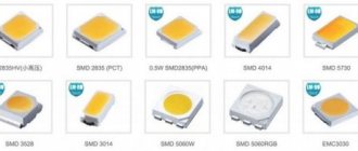
Types of SMD LEDs and their features
Let's consider the classification of SMD diodes according to their design features, as well as the most popular models used in a variety of lighting products.
Single-, double-, triple-chip SMD LEDs
Single-chip – consist of one monochrome crystal and differ in power/brightness levels. Low-power models consume current up to 20 mA and produce a luminous flux of 5-50mCd and 100-2000mCd, depending on the modification. The crystal is covered with a lens having a flat or spherical shape. Higher-power LEDs require 50mA to 1A of current and a heat-efficient design.
Multi-crystal - contain a different number of crystals, allowing you to provide the desired brightness and color palette of the glow. The operating voltage varies and is standardized by manufacturers. For example, Cree products operate on a power supply of 6-72 V with power up to 25 W.
Glow color
LEDs are available in 2 varieties, differing in the method of color formation:
- single-color – based on single-chip chips that emit white, yellow and other primary colors;
- multicolor - have a three-crystal structure consisting of chips that glow red/green/blue. These base colors are mixed to create hundreds of color shades. Light fluxes from 3 crystals are combined into a single light beam with or without an optical lens due to their spatial addition. An RGB controller is used to adjust the color palette and brightness.
Standard size
The standard sizes of SMD diodes are coded with a four-digit number indicating their linear dimensions. Here are the most common options:
SMD3528
– a low-power model with low energy efficiency. A cost-effective solution for dim LED strips. Rectangular case measuring 3.5x2.8x1.4 mm.
SMD5050
– a chip of 3 3528 crystals with green, red, blue glow and three times the total brightness. Dimensions 5.0x5.0x1.6 mm. Square body with six pins.
SMD2835
– a single-chip chip with low power consumption and fairly high power. Size 2.8x3.5x0.8 mm. Increasing the contact area allowed for improved heat dissipation. A layer of phosphor coating increases the intensity of the light flux.
SMD5630
- a type of powerful light-emitting device with high brightness. Size 5.6x3.0x0.77 mm. Equipped with four terminals.
SMD5730
– is almost a complete analogue of the previous model. There are modifications 5730-05 and 5730-1.
SMD3014
– a variation of a powerful LED source with a light beam size of 9-11 lumens. They are produced on the basis of chips with different numbers of crystals. The increased area of the heat-dissipating substrate promotes efficient removal of thermal energy.
You can find SMD LEDs of standard sizes 3030, 7020, 8520, which are used much less frequently. Manufacturers periodically release new LEDs onto the market, the parameters and characteristics of which differ significantly. The problem of how to determine the parameters of an LED is solved similarly to other models.
How to connect an LED to blink
The simplest scheme
The first scheme has been used for a long time. It is already known in the USSR and is based on the avalanche breakdown of the collector-emitter junction of a bipolar transistor. The capacitor is charged from the mains, and the voltage is divided between the LED and the semiconductor switch. The resistor and capacitor values determine the charging time constant and, as a result, the blinking frequency.
An avalanche breakdown is similar to an electric arc and exhibits a negative differential resistance. While the charge on the capacitor drops, the LED operates quietly. Finally, the potential difference reaches a certain threshold, the pn junction closes. More precisely, there are two pn junctions between the emitter and collector. From the above it follows that the transistor can be replaced by any nonlinear element that demonstrates a current-voltage characteristic with a negative differential resistance. This group includes avalanche and tunnel diodes.
Most bipolar transistors exhibit the desired characteristic. The one whose maximum emitter-collector reverse voltage is less than the applied power is selected. Avalanche breakdown is more easily observed at the emitter junction. Accordingly, it will need to be turned on in the opposite direction.
Generator circuits
A multivibrator circuit is being discussed on the Internet. There are other generators that are useful due to their ease of assembly and setup. Relay devices are still used today. They are classified as contact generators, indicating the presence of moving parts.
A pulse pair, built from two relays, has a simple advantage - obvious operation, no measuring devices are required for debugging. The figure shows a possible implementation of a circuit using electromagnetic opening and closing relays. At the initial moment of time, power is supplied through the 2P contact to the 1P coil. As a result, the first relay closes. 2P receives power and:
- It breaks its contacts in the output circuit where the LED is located. It goes out.
- Stops feeding 1P.
The power to the 1P relay disappears, it opens. As a result, the normally closed 2P contacts return power to the LED and 1P. The circuit is rolled back to its original state, and a new cycle of work begins. The switching speed is determined entirely by the characteristics of the relay. For additional adjustment, it is permissible to add response-delaying elements to the circuit.
The second picture shows a generator that was widely used in technology. It consists of a pulse pair, the operating mode is discussed above, and an auxiliary relay with a time delay task. Control buttons (CU) set the required parameters.
When you press the button, the device starts working. The brushes of the step finder (SHI) move from lamella to lamella. Switching in progress. First, through lamella 0, button and coil 1P, the potential is supplied to relay 1P. It fires and does the following:
- It breaks the power supply circuit of the 2P coil, where the current previously flowed.
- Prepares relay D for operation.
When the brush moves to lamella 1, relay 1P is de-energized, relay 2P opens its contacts. Relay 1P disappears. 2P turns on, supplying power to 1P. The circle closes. An LED is connected to the second pin 2P and begins to blink.
If KU is pressed, the SHI brush hits the second lamella, and when 1P is turned on, relay D will operate. The latter will temporarily slow down the switching of 2P. In this case, the LED will temporarily stop blinking and the period will lengthen.
Multivibrator circuit
Multivibrators are transistor generators of rectangular pulses. Due to their characteristics, power elements are often chosen to be bipolar. According to the classification, multivibrators belong to contactless generators and are often used to power LEDs, causing them to blink.
Transistors are easier to obtain than specialized microcircuits, which determines the popularity of the proposed technical solution. Contactless generators have a long service life, and the switching speed is adjusted by choosing the ratings of the passive elements. Multivibrators produce rectangular pulses. However, similar things are said about contact generators. In this case, this is good.
According to the circuit, the collector voltage of the second is supplied to the base of the first transistor through a capacitor, opening the switch. At this moment, two processes occur simultaneously:
- The control capacitor is discharged through the outer resistor and the emitter-base junction of the opposite transistor.
- Another capacitor is charged through its collector and internal resistor.
The circuit works like a swing, which, however, is typical for any rectangular pulse generators. With the values C and R it is permissible to change the oscillation period and duty cycle. The latter is achieved in an asymmetrical circuit.
Generators on chips
The timer on the 555 series chip allows you to make the LED blink in simple ways. To do this, radio amateurs use a standard 9-volt battery. A few resistors, a microcircuit and a capacitor are all that is needed in the described situation. As before, the time constant is set by the dimensions of the passive elements of the capacitor. To debug the circuit, it is possible to use a tuning or variable capacitance.
Rating of SMD LEDs
| Place | Manufacturer | A country | Product Features |
| 1 | CREE | USA | Use of high performance InGaN materials with patented G SIC ® substrate |
| 2 | NICHIA | Japan | Serves as a calibration standard for luminous and emitted quantities for LED products used by the National Institute of Advanced Industrial Science and Technology (AIST). Features uniform spatial light distribution, excellent temperature stability and lighting reproducibility |
| 3 | TOYODA GOSEI | Japan | Known for LEDs that reproduce light 99% close to sunlight. Develops deep ultraviolet light modules effective in combating viruses and bacteria |
| 4 | OSRAM | Germany | There are many innovative developments, such as UV-C LEDs, which emit in the UV spectrum and are capable of disinfecting air, water, and work surfaces. Produces light-emitting diodes of almost all types |
| 5 | Lumileds | Europe | Famous for its high quality, thanks to strict control of materials and technological processes, comprehensive testing of finished products |
How to correctly decipher the marking?
SMD LED markings provide the user with brief information about the products. For example, we have a light-emitting diode labeled SMD 2835 UWC 5. We decipher: standard size 2835 with dimensions 2.8x3.5 mm, power 0.5 W, white tint.
| SMD type | Number of crystals | Dimensions, mm |
| 3528 | 1 | 3.5x2.8x1.4 |
| 5050 | 3 / 4 | 5x5x1.6 |
| 5630 | 1 | 5.6x3x0.75 |
| 5730 | 1 / 2 | 5.7x3x0.75 |
| 3014 | 1 | 3x1.4x0.75 |
| 2835 | 1 | 2.8x3.5x0.8 |
How to identify an LED by appearance?
Measure the dimensions of the diode using any ruler. Look for sizes in the table, determine the type of product and see its characteristics.
| SMD type | Number of crystals | Dimensions, mm | Power, W | Current, mA | Light flux, Lm |
| 3528 | 1 | 3.5x2.8x1.4 | 0,02 / 0,06 | 20 | 5-7 |
| 5050 | 3 / 4 | 5x5x1.6 | 0,02 | 60 / 80 | 18-20 |
| 5630 | 1 | 5.6x3x0.75 | 0,2-0,4 | 150 | 58 |
| 5730 | 1 / 2 | 5.7x3x0.75 | 0,5 / 1 | 150 / 300 | 50 / 158 |
| 3014 | 1 | 3x1.4x0.75 | 0,1-0,12 | 30 | 9-13 |
| 2835 | 1 | 2.8x3.5x0.8 | 0,2 / 0,5 / 1 | 60 / 150 / 300 | 20 / 50 / 100 |
How to determine the polarity of an LED?
In the transparent body of the output LED, you can see the anode and cathode of a characteristic shape.
On SMD packages, an angular cut is visible, indicating the cathode terminal. On the back side there is a heat sink pad, shifted towards the anode.
Another indicator of polarity are the pictograms: triangle, letters P and T. The direction of the letter protrusions and the apex of the triangle points to the cathode.
Types of white LEDs
Depending on the operating principle, there are two types of white LEDs:
- phosphor;
- multi-chip.
In addition, they differ in power, color temperature, size, light dispersion angle, etc. The most common among white chip LEDs are thin plates measuring 5mm by 5mm or 3.5mm by 2.8mm, but smaller and larger sizes are also available.
Each manufacturer indicates in his opinion the most necessary characteristics, but they always include electrical and color parameters.