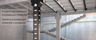
Mounting elements, as a rule, are supplied not individually, but in an assembly, ready for installation. Therefore, we will immediately consider the attachment points for crane beams and crane rails: we will find out what components they can include, what requirements are imposed on them in accordance with current interstate standards, and so on.
Let us note right away: they are used everywhere - in all those cases where laying a railway track, along which special cargo equipment or rolling stock will subsequently move, is generally relevant. They are used on such objects as:
- open areas,
- overpasses of small and medium length,
- workshops, warehouses and other closed premises.
Why are they so in demand? Because each VSP metal structure must be securely fixed so that it does not move, does not disturb the perfectly even geometry of the track, and does not provoke derailments (after all, they are fraught with injuries, material losses, repair costs and other unpleasant consequences).
Mounting points for crane rail to beam
In general, they consist of the following components:
- strips - clamping and thrust, P1/P2 and U1/U2/U3, respectively, depending on the type and brand of guides taken;
- overlays - for normal and temperature-controlled joints, from the KR and TS lines (again, depending on what metal profiles are laid;
- a set of bolts, nuts and washers to connect all VSP elements to each other and securely fix them on the supports.
In some situations, installation is possible using “cockerels” and two- and single-hole slats, using hooks and shaped plates for welding. Although, if we consider the tracks for special cargo vehicles, it is better that the joints are prefabricated and not suture - then it will be possible to remove only one damaged I-beam without wasting time, and not the entire section at once, and carry out prompt repairs or replacement. The main thing is that non-standard options are always discussed with the supplier (manufacturer) separately.
Types of connections
Please note that fastening the P43 (P24, etc.) rail to the crane beam, according to GOST 24741-81, can be one of two options:
- or allowing straightening (straightening);
- or motionless.
Let's look at each of them.
Movable
The previously mentioned collapsible is its bright representative. In addition to the obvious advantage - a high degree of maintainability - it has one important feature: it simply needs to be carefully debugged during the installation process. Otherwise, if the lining or steel strip does not fit tightly, a gap will inevitably form, and if the bolts are tightened too tightly, a point of concentration of excess stress will form. All these problems will quickly lead to damage, and when it begins to spread along the profile, this will result in the failure of the transport track section.
motionless
It is welded, and is only relevant when the equipment is expected to operate only in light mode. In other situations, each seam will be a dangerous area that can provoke an accident.
An interesting alternative for fastening crane runway rails is with hooks: they need to be placed every 500-700 mm, and directed away from each other.
If the selected guides are block-shaped, then before welding they should be straightened, and very carefully.
This installation involves planing grooves and using strips with special oval holes for bolts. In this case, it is necessary not to bring the lining to the profile, leaving a gap of 10-20 millimeters so that alignment can be carried out later. Having made it and inserted the slats, welding should be carried out.
At the same time, it is highly not recommended to simplify the technology and make the connection “directly,” that is, without grooves. If you do this, you will get too weak seams that are easily destroyed under significant, continuous and impact loads. To avoid having to spend money on expensive repairs of the transport roadway, it is better to immediately resolve the issue efficiently.
Fastening the crane rail to the crane beam
It must be as reliable as possible to ensure long-term and trouble-free operation. Therefore, it is important to choose the right metal profiles, and they can be either ordinary railway ones, or oriented towards special bridge equipment from the KR line, or even rectangular bars - any options approved by the interstate standard 4121-48 are welcome.
Which option should you prefer? This depends on the intended operating mode, the load capacity that needs to be provided for a long time, the installed running wheels (what type are they, conical or cylindrical?) and other, less significant factors.
The square rail is fastened using at least two bolts, always taking into account the cross-section of the support and the fact that during a strength test it will be weakened by just a pair of selected connectors. If profiles from the KR line are mounted, special tabs cut from a corner are additionally used.
Please note that the beams can also be different. The most popular of them today are:
- Horizontal brakes are made of steel (corrugated metal 6-10 mm thick), with a standard upper belt and another one made from an angle or channel. As a rule, they themselves are fixed to overlying surfaces (most often, on ceilings), especially if their span is more than 12 m in length. In such cases, installing an additional strut is usually not required and is not even recommended.
- Solid – a real classic for fastening gantry crane rails. For special equipment with a relatively low carrying capacity (3-5 tons), ordinary single, six-meter ones will suffice, but for powerful models (5-30 tons), it is necessary to install composite ones, the cross-section of which is asymmetrical - they will cope with the load, including due to developed belt.
- Lattice - very well suited for long spans, from 18 m or more. Their upper part is made of trusses made of a fairly rigid I-beam, which does double work - both for local bending and for compression across the section. Other section surfaces are usually formed by a pair of corners. Not inferior to their competitors in strength, they are significantly lighter, which only expands the scope of their use.
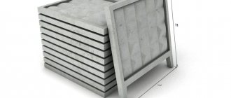
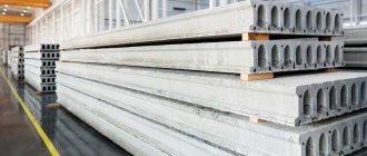
Reinforced concrete crane beams
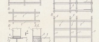
Crane beams with rails laid on them form the movement paths of overhead cranes. They also give the building additional spatial rigidity. Reinforced concrete crane beams can have a T-section or an I-section (Fig. 5.15). The first are provided with a column spacing of 6 m, the second - with a column spacing of 12 m. Reinforced concrete crane beams are installed under cranes with a lifting capacity of up to 32 tons.
Rice. 5. 15. Reinforced concrete crane beams: a)
– with a column spacing of 6m;
b)
– the same, 12 m.
The wide flange of the beam serves to strengthen the compressed zone. It absorbs transverse horizontal crane loads and also simplifies the fastening of crane rails. The height of the beams is 800, 1000 and 1400 mm, the width of the shelves is 550, 600 and 650 mm.
For the manufacture of crane beams, concrete of class B22.5–B40, welded frames are used, and for the lower chord - prestressed rods, string packages or strands of high-strength wire. The beams contain embedded elements for fastening to columns (steel plates) and for fastening rails and trolleys (tubes).
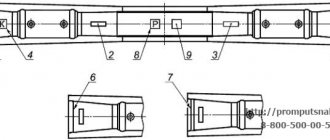
The beams are secured to the columns by welding embedded elements and anchor bolts (Fig. 5.16, a). After aligning the beams, the nuts of the anchor bolts are welded. The rails with the crane beams are connected by paired steel legs located every 750 mm (Fig. 5.16, b). To reduce dynamic impacts on beams and reduce the noise of moving cranes, elastic pads made of rubberized fabric 8-10 mm thick are placed under the rails.
a) b)
Rice. 5.16. Reinforced concrete crane beams: a)
fastening reinforced concrete crane beams to columns;
b)
fastening the crane rail to the column.
1
– supporting steel sheet (160x12x500mm);
2
– anchor bolt;
3
– steel plate (100x12mm);
4, 5
– embedded elements of the column;
6
– steel foot;
7
– bolt;
8
– elastic gaskets 8 mm thick;
9
– crane rail.
To avoid impacts of overhead cranes on the columns of the building's end frame, steel stops with shock absorbers - buffers made of wooden beams - are installed at the ends of the crane runways.
The use of reinforced concrete crane beams should be limited. This is due to their large mass, relatively short service life, since they experience dynamic loads, and the difficulty of straightening crane runways.
2.4. Strapping beams
Strapping beams are used to support brick and small-block walls in places where there is a difference in heights of adjacent spans, as well as to increase the strength and stability of high self-supporting walls. In the latter case, the distance between the beams in height is determined by calculation depending on the height, thickness and material of the wall, the presence of openings in the wall and their sizes. The walls of the second and subsequent tiers are curtain walls (the loads from them are transferred to the columns, while the first tier of the wall, resting on the foundation beam, is self-supporting). Trim beams are usually placed above window openings, and they act as lintels. Such beams have a rectangular cross-section with a side of 585 mm, their width is 200, 250 and 380 mm, and their length is 5950 mm. The strapping beams are made from B15 concrete and reinforced with welded frames with working reinforcement made of class A-III steel. The beams are laid on steel support console tables with a hidden stiffener and secured to the columns with steel strips (Fig. 5.17).
Rice. 5.17. Strapping beams and their fastening to columns: 1
– steel support table;
2
– steel strip;
3
– welding.
2.5. Connections by columns, trusses.
To increase the stability of one-story buildings in the longitudinal direction, a system of vertical and horizontal connections is provided between the columns of the frame and in the roof.
Vertical connections
with reinforced concrete frame columns in buildings without overhead cranes and with overhead transport, they are installed only when the height of the rooms is more than 9.6 m. They are located in the middle of the temperature blocks in each longitudinal row of columns. When the column spacing is 6 m, longitudinal struts are additionally installed on the top of all columns. In buildings equipped with overhead cranes, connections are installed in the crane section. The connections along the columns are made cross and portal (Fig. 5.18). The shape of the connections depends on the pitch of the columns, the height from the floor to the head of the crane rail and the type of floor transport. Cross braces are most often used with a column spacing of 6 m, a height to the crane rail head of up to 10 m and small-sized floor-standing transport, and portal bracing is used with a spacing of 12 m or more in taller buildings using large-sized transport (cars, stackers, etc.).
Rice. 5.18. Connections between reinforced concrete columns: 1
– cross-type connections;
2
- the same, portal.
Connections in coatings
are selected taking into account the type of frame, type of coating, height of the building, type of in-shop lifting and transport equipment, its load capacity and operating mode.
Vertical connections between the supports of reinforced concrete truss structures are installed only in coverings with a flat roof. In buildings without rafter structures, such connections are placed in each row of columns, and with rafter structures - only in the outer rows of columns at a pitch of 6 m.
Between the supports of trusses or beams, vertical connections are installed no more than after one column spacing. In places where there are no vertical connections, spacers are placed on top of the columns (Fig. 5.19).
Rice. 5.19. Connections in coatings at a pitch of 6 m in craneless buildings without rafter structures: 1
– vertical connection across farms;
2
– spacer.
Along the middle rows of columns, the outermost trusses in each temperature block are connected to the upper chords of the trusses with horizontal struts (Fig. 5.20).
Rice. 5.20. Connections in coatings at a pitch of 6 m in craneless buildings with rafter structures: 1
– horizontal strut along the rafter trusses
In the coverings, when the column spacing of the outer and middle rows is 12 m, horizontal braced trusses are provided, placing them at the level of the lower chord of the trusses at the ends of the temperature blocks in each span (Fig. 5.21).
Rice. 5.21. Coating connections at a pitch of 12 m in buildings with overhead cranes: 1
– vertical connection along the farm;
2
– spacer;
3
– connection by columns;
4
– horizontal truss at the ends.
In buildings with heavy-duty overhead cranes or process equipment that causes frame vibrations. In the middle of each span, spacers (strands) and vertical connections are placed along the lower chord of the rafter structures. The role of horizontal connections in the upper chords of trusses or beams is performed by large-sized covering panels.
Vertical and horizontal connections of the coating are made of angles, channels and pipes and secured to reinforced concrete structures with bolts and welding.
In spans with lanterns, horizontal cross braces are installed at the ends of the lantern openings. Within the length of the lantern opening, spacers are installed along the ridge of the trusses.
Pressure and thrust bar
These are key parts for fastening crane rails and are included in any mounting assembly. Actually, the kit itself consists of just these, as well as linings and a set of bolts, washers, and nuts.
Can be designed for two operating temperature conditions:
- normal – up to -40 0С and above;
- hard - in conditions of -40...-65 degrees Celsius.
In the second case, they get the suffix “HL” in the name. U1 becomes U1HL, P2 - P2HL and the like. Naturally, you need to choose specific elements for the climate in which they will be used. Otherwise, the element will wear out very quickly and require replacement, and will also provoke the appearance of a gap or, conversely, a point of stress concentration, that is, a place where a defect forms over time.
The bolts for fixing the thrust and clamping bars must be checked for tensile strength before use - in accordance with the requirements of GOST R ISO 898-1-2011, and this is for normal operation. If they are selected for a cold climate, they should also be tested for impact strength.
Attention, there are certain tolerances between actual and calculated dimensions. Although the error must still be minimal and fit within the permitted deviations. It’s the same story with roughness: it can be present, but should not be higher than a certain value. Well, interstate standard 25347-82 establishes the difference between the practical and theoretical diameter of a technological hole.
Specifications
They fully regulate the fastening of crane track rails to steel beams for organizing the movement of electric overhead cranes and are dictated by GOST 4121-76. According to this standard, transport lines created in this way can be operated in light, medium and even heavy duty. Objects for laying lines are allowed to be very different, up to open and fairly long overpasses.
The maximum calculated seismicity is 9 points on the MSK-64 scale, the ambient temperature can reach -65 degrees Celsius.
They also set the center distance between the supporting structure and the central installation point. It, along with other important geometric parameters, is presented in the drawing and table below.
| Rail type | Mounting unit brand | Distance between axes Ah, mm | Planks | screw | Bolt | Washer | |
| clamping | stubborn | ||||||
| KR70 | 70 | 95 | P1 | U1 | M 24.4 GOST 15526-70 | M 24x46 GOST 15589-70 | 24.02 GOST 11371-78 |
| KR80 | 80 | 100 | P2 | ||||
| KR100 | 100 | 110 | P1 | U2 | |||
| KR120 | 120 | 120 | U3 | ||||
| KR70 | 70HL | 95 | P1HL | U1HL | M 24.4 GOST 5915-70 | M 24x46 GOST 7798-70 | |
| KR80 | 80HL | 100 | P2HL | ||||
| KR100 | 100HL | 110 | P1HL | U2HL | |||
| KR120 | 120HL | 120 | U3HL | ||||
When deciding which attachment point for crane rails to reinforced concrete beams to choose, remember the connectors. In the case of fixation elements, the following rule applies:
l, that is, the estimated length of the bolt, must be taken based on the following ratio:
(80 + b) mm – if preference is given to KR70-100 profiles;
(85 + b) mm – if KR120 will be used;
and in this formula:
- 80 and 85 – the total (total) thickness of the elements, already taking into account that nuts, washers, and other components may be tilted, and taking into account the effect that is observed in this case;
- b – average thickness of the supporting structure, presented in millimeters and taken in the central part of the upper chord.
Scope of practical application of rolled metal
The universal I-beam is widely used and is used for various types of construction work, for the construction of all kinds of buildings and structures.
Such products are used for large-panel buildings with different numbers of floors, private houses and cottages, commercial and industrial buildings as load-bearing elements:
- for arrangement of crane beams in production workshops and warehouses;
- columns, supports of bridges and viaducts, urban and suburban overpasses;
- as a reliable structural element of overpasses and roads;
- during the construction of supporting structures for the shoreline and pits;
- to strengthen fastening elements of underground structures;
- as supporting structures for automobile and railway tunnels;
- in the manufacture of loading and cargo platforms and transport vessels.
When choosing a product, a table of I-beams is used, which indicates the main parameters of rolled metal products. The I-beam can additionally be used for the manufacture of T-profiles, for which the workpiece is cut lengthwise using modern equipment; these profiles are used for lattice-type structures.
Clamping strips GOST 24741-81
They are required to be included in the rail fastening unit to the crane beam of series 1.426.2 and its subcategories, being one of the key elements of the assembly. Their important practical advantage is a long service life even in frost conditions and seismic resistance - their powder is higher than the design load of 9 points according to MSK-64, they remain unharmed where brick walls are destroyed.
In order not to repeat ourselves, let's move on to other advantages, namely the low maintenance requirements. Yes, this element experiences good loads during operation, but it does not need to be strengthened with anything additional - it is enough just to regularly inspect it for damage and take timely measures.
The clamping strip for fastening crane rails to metal beams may also have the following features:
- Made using the bending method (gouging is not the only method for manufacturing), and other elements of the kit can also be made using this technology, taking care to maintain the required slope; it is important that the errors do not exceed the permissible values regulated by interstate standard 24741-81.
- The set of bolts, washers and nuts may be non-standard, but only with prior approval of this point with the manufacturer or supplier.
- An unusual number of process holes is also acceptable; for example, by ordering directly from the manufacturer, you can negotiate and receive a batch of planks with one seat rather than two.
- In general, these elements are compatible with a wide range of profiles - with the narrow-gauge R-24, and with the original R-43, and with the massive KR-120; If you select the right one, there will be no problems with installation.
Lining material
According to current GOSTs, the attachment point for crane rails to a reinforced concrete crane beam can be supplemented with an elastic layer, which must be placed under the bar. A conveyor belt with the following characteristics will perform this role well:
- 500 mm width with 6 mm thickness;
- footage in the bay is 100 m.
If we consider other, more specific connectors, it is worth paying attention to the hooks: with their help you can securely fix the P-50 or P-43, the main thing is to select them, focusing on the width of the upper chord of the supporting structure and the diameter of the technological holes. Even more non-standard options, but still finding limited use, are staples.
Now let's move on to another group of elements that help ensure high quality and proper installation reliability.
Definition and distinctive features of the product
Looking at the presented photos of an I-beam, you can see the distinctive feature of such rolled metal products. This is an H-shaped cross-section, thanks to which the I-beam is characterized by increased strength parameters, and the economical consumption of building materials determines the high demand for the product.
The peculiarity of the section makes it possible to widely use the beam in construction and construction of structures for various purposes.
Moreover, such structures help to distribute the load evenly along vertical and horizontal guides, to increase the stability and reliability of the building.
In construction, along with metal I-beams, products made from other metals and even wood are used.
Metal profiles are more in demand due to their strength and resistance to mechanical and physical damage; they are manufactured in two ways, which include:
- hot rolled technique;
- welded production method.
The material used to manufacture rolled metal products is carbon and low-alloy steel.
The manufacturing technology involves the use of modern rolling mills and a specific production cycle, which makes it possible to give the products a set of unique performance characteristics.
Butt pads
Let's see what one of them looks like, designed for attaching the KR-70 crane rail to the crane beam: its design (as well as the element for any other profile in the series) with all the important dimensions is presented in the drawing and in the tables below.
| Rail type | Joint grade | Weight, kg | Note |
| KR70 | RS 3 | 3,4 | 16 |
| KR80 | |||
| KR100 | RS 4 | 5,02 | 20 |
| KR120 | RS 5 | 7,2 | 25 |
| KR140 | RS 6 | 9,7 | 30 |
It should be noted here that these components can be custom-made to fit the neck, and in this case the contact surface will be radius.
In addition, the following elements can be selected for the clamping bars:
- engraving washer 24,
- nut M24,
- M24 bolt 90 ... 140 mm (its length should be measured without a head).
Why you should buy the right equipment
Reinforced concrete and steel crane beams can withstand both permanent loads and one-time use. The high performance of this element of metal structures depends on correct installation and accurate calculations.
The leading manufacturer of lifting equipment, LLC Krankomplekt Plant, produces crane beams of various types, the price of which is the most favorable in both the Ukrainian and European markets, because the cost of equipment does not increase due to intermediary markups. More detailed information about the crane beams of this enterprise can be obtained on the page https://krankomplekt.com/nestandartnoe/podkranoviy/. The company's experienced consultants will help you select the most suitable crane tracks. Delivery of goods is carried out not only in Kyiv, but also in other cities of the country.