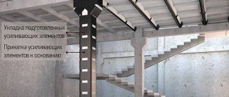
Acceptance control is carried out by quality service workers, foreman, and representatives of the customer’s technical supervision. Technical requirements and maximum deviations SNiP 3. The magnitude of failure of driven piles should not exceed the calculated value The same. Amplitude of oscillations at the end of vibration immersion of piles and pile-shells The same The same. Continuity of the shaft of piles made by the method of underwater concreting. The shaft of the pile should not have any discontinuity. Measuring, testing of samples taken from cores drilled into piles or in another way.
Continuity of the trunk of hollow cast-in-place piles The trunk should not have concrete spills with an area exceeding cm2 or exposures of working reinforcement Visual, each pile. Stages of work.
SNiP provides for permissible deviations of piles in plan from the design position depending on their location, length and diameter. The values of permissible deviations are given in table. To control the position of the pile driver mast, they use devices that record its deviation from the required one. The use of materials is permitted only with the obligatory installation of an active hyperlink to the Svaika website. Ru next to the published material.
Controlled operations. Control method, volume. Passport certificates, inspection report of hidden work, general work log. Visual, measuring.
Driving piles and cutting down pile heads.
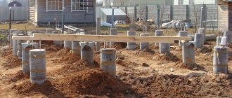
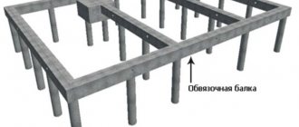
Description of a pile foundation with a grillage
The name of the pile foundation already suggests that it consists of piles that are buried in the ground to a certain level. Most often, piles are immersed to a dense load-bearing soil layer or below its freezing level. The finished pile structure cannot be used in its pure form, as it consists of disparate elements. The exception is frame buildings or log buildings made of timber or logs, in which the lower crowns are capable of taking on the load of the entire building.
Pile foundation with grillage
For the construction of houses from other types of material, a more advanced form is used - a pile grillage foundation. In this design, the above-ground parts of the piles are connected by a metal or concrete strip or grillage.
In professional language, a grillage is the part of the base that connects the pile heads and serves as a support for load-bearing walls.
Permissible deviations of pile heads after felling
The acceptance certificate for the pile driver is drawn up in three copies: the first is stored at the place of work of the pile driver with the manufacturer of the work, the second - with the chief mechanic of the construction organization and the third - in the mechanization department of the owner of the pile driver or the base machine of the crane, excavator, tractor.
The installation of grillages or the installation and embedding of prefabricated caps is carried out by a foundation construction trust or a general construction trust, which are general contractors. The installation of a grillage is permitted after the pile field has been accepted by a representative of the designer's supervision and a corresponding act has been drawn up. The piles are cut down after acceptance of the pile field. The cutting of piles and embedding of their heads into the grillage must be carried out in accordance with the project.
The upper ends of the piles embedded in the grillage must be horizontal. The concrete of the piles should not have cracks or chips that reduce the protective layer of reinforcement at the junction points between the piles and grillages.
The piles must be embedded in the grillage to a depth of at least 50 mm from its bottom. The base for a monolithic grillage must be carefully planned according to design marks and compacted.
The choice of the design of a pile foundation, on a natural or artificial foundation, as well as the type of piles and the type of pile foundation, for example, pile bushes, strips, fields, should be made based on the specific conditions of the construction site, characterized by engineering survey materials, design loads acting on the foundation, based on the results of a technical and economic comparison of possible options for design solutions for foundations with an assessment of reduced costs, carried out taking into account the requirements for the economical use of basic building materials and ensuring the most complete use of the strength and deformation characteristics of soils and the physical and mechanical properties of foundation materials.
Pile foundations should be designed based on the results of engineering-geodetic, engineering-geological, engineering-hydrometeorological surveys of the construction site, as well as on the basis of data characterizing the purpose, design and technological features of the designed buildings and structures and their operating conditions, loads acting on the foundations, taking into account local construction conditions.
Types of pile foundation depending on the driving method
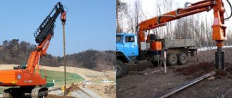
Piles can be made in different ways, which determines the method of immersion in the ground:
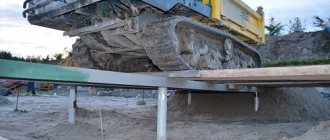
- Driven piles are driven into the ground only using special equipment or a vibratory driver.
- Cast-in-place piles are driven into the well using a drill and filled with concrete. Made from concrete or reinforced concrete.
- Drilled piles are reinforced concrete products immersed in a pre-drilled hole.
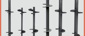
- Screw piles are metal posts with a screw-shaped tip. Immersion is carried out by directly screwing the pile into the ground.
SNiP 2.02.03-85. Cast-in and bored piles
The design of pile foundations without an appropriate and sufficient engineering-geological justification is not allowed. The results of engineering surveys must contain the data necessary to select the type of foundation, including a pile, to determine the type of piles and their dimensions, cross-sectional dimensions and length of the pile, the design load allowed on the pile, taking into account the forecast of possible changes during the construction and operation of the engineering -geological and hydrogeological conditions of the construction site, as well as the type and scope of engineering measures for its development.
The survey materials should contain data from field and laboratory studies of soils, and, in necessary cases established by the design organization designing pile foundations, the results of tests of full-scale piles with static and dynamic loads. Geological sections with data on soil strata, calculated values of their physical and mechanical characteristics used in calculations for two groups of limit states, indicating the position of the established and predicted groundwater levels, and, if sounding results are available, sounding graphs should also be provided.
Testing of piles carried out during the construction process in accordance with the requirements of SNiP 3. Projects of pile foundations should provide for full-scale measurements of deformations of foundations and foundations in cases of using new or insufficiently studied structures of buildings and structures or their foundations, construction of critical buildings and structures in complex engineering - geological conditions, as well as if there are special requirements for measuring deformations in the design assignment.
Pile foundations intended for operation in aggressive environments should be designed taking into account the requirements of SNiP 2. Based on the method of deepening into the ground, the following types of piles should be distinguished: a driven reinforced concrete, wooden and steel, immersed in the ground without excavating it using hammers, vibratory hammers, vibrating and pressing devices, as well as reinforced concrete shell piles, buried by vibratory drivers without excavation or with partial excavation of soil and not filled with concrete mixture;.
Notes: 1. When determining the load-bearing capacity of screw piles under the action of indenting loads, the soil characteristics in Table.
Calculation of the number of piles for the foundation
The reliability of the erected structure largely depends on the correct calculation of the number of supports and the distance between them, since they take on the main load and distribute it. When making calculations, it is necessary to take into account:
We count the number of piles
- The approximate weight of the structure, including floors, walls, ceilings and cladding.
- Payload from furniture, appliances and occupants. Most often, this parameter has a constant value: for multi-story structures - 200 kg/m2, for residential one-story buildings - 150 kg/m2.
- Load from snow cover in winter. This value is also constant; in most regions it is 180 kg/m2.
- The safety factor, which in most cases is equal to 1.1 (a factor of 1.2 is very rarely used).
For example, you need to calculate the number of piles and the pitch between them for a building one floor high and 6*8 meters in size:
- We determine the weight of the structure; for example, we can take 29,500 kg.
- We calculate the total payload; for this, we multiply the value indicated per 1 sq.m. by the area of the house: 6*8*150=7200 kg.
- Let's find out the amount of snow load taking into account the area of the house: 6*8*180=8640 kg.
- We determine the total load on the base; to do this, we sum up the load of the structure, the payload and the snow load: 29500+7200+8640=45340 kg.
- The resulting value must be multiplied by a safety factor of 1.1: 45340*1.1=49874 kg.
- Taking into account that on average one pile can withstand a load of about 2000 kg, we determine the required number of piles. To do this, it is enough to divide the value of the total load, taking into account the safety factor, by the possible load on one pile: 49874:2000=24.937.
Counting steps between piles
When rounding this number, we find that for a one-story house with an area of 48 sq.m. 25 piles are needed. To this amount you need to add piles that will support the floor joists inside the foundation.
The step between the supports of the pile foundation is determined to be 1.2-1.5 meters.
Application area
1.1. The technological map has been drawn up for the work of driving composite reinforced concrete piles at Glavmosstroy facilities.
1.2. The works covered by the map include:
territory planning;
geodetic layout of axes and pile driving locations;
immersion of the lower pile;
joining the lower and upper piles;
final driving of a composite reinforced concrete pile.
1.3. The technological map is intended for drawing up work projects and for the purpose of familiarizing workers and engineers with the rules for carrying out work.
1.4. When linking the technological map to a specific object and construction conditions, the work flow diagrams, volumes of work, calculation of labor costs, and mechanization means are specified.
Location of piles in the grillage
Depending on the grillage design, the piles may have different locations:
Location of piles in the grillage
- Single piles are each located under its own support.
- The strip arrangement implies an even distribution of supports around the entire perimeter of the house.
- Cluster arrangement is necessary in places where increased load on the base is expected.
- When arranged in a field, the piles are distributed in rows or in a checkerboard pattern.
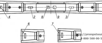
Purpose of composite reinforced concrete piles
2.1. Composite reinforced concrete piles are used in cases where the use of piles less than 12 m in length is impossible due to soil conditions.
2.2. Composite piles are used for constructing foundations of residential, civil and industrial buildings and structures for the conditions of Moscow.
2.3. Composite piles can be used in all types of soils. Supporting piles when layers of soft soils lie at a depth of more than 9 - 11 m is impossible due to deformability conditions.
2.4 Composite piles are intended for use in the foundations of buildings and structures with the transfer of vertical compressive loads to them.
2.5. For load-bearing work, composite piles can only be used as anchor piles during static tests.
The joints of composite piles are also tested for load bearing capacity.
2.8. Composite piles can be used both as hanging piles and as rack piles.
2.7. The use of composite reinforced concrete piles for foundations for equipment with large dynamic loads is not recommended.
DIY pile foundation with grillage
Most often, the construction of houses is carried out on a bored pile foundation with a grillage in the form of a concrete strip, which is located above the ground at a distance of 0.2 meters or buried in the ground.
The construction of a pile foundation with a grillage is carried out in several stages.
Site marking
To build any foundation, correctly executed markings are required; a pile grillage foundation also cannot do without this stage. The site is marked as follows:
Marking the area
- Along the line of location of one of the long sides of the house, two pegs are placed, the distance between which is equal to the length of this side. These will be the two corners of the house. A construction cord or rope is pulled between the pegs.
- Two more cords are pulled perpendicular to the resulting line, on which the width of the house is marked, and pegs are set. Two other corners will be located here, they are also connected by a cord.
- You can check the correctness of the angles in the following way: make a mark of 3 meters on one side of the corner, and 4 meters on the other. If the angle is right, then the distance between the marks will be 5 meters.
- Then mark the places where the foundation supports will be located. It is important here that the piles are placed at the corners of the house and at the intersections of the walls.
Excavation
You can make holes for piles yourself using a hand drill. The depth of the wells is determined at the design stage, but most often it is 1.5-2 meters.
A layer of sand is poured onto the bottom of the drilled holes to create a cushion. The thickness of the layer must be at least 0.1 meters, it must be compacted very well.
An asbestos-cement pipe is installed on the cushion, strictly monitoring the vertical position of the support. You can use a building level to check.
Reinforcement of supports
To create a reinforcing frame, take four reinforcement rods with a cross-section of 12 mm and tie them with crossbars using soft wire. The height of the frame should be equal to the height of the support with a margin of 20 cm. This margin is necessary for further connection with the grillage.
Preparation and pouring of concrete
It is necessary to fill the piles with a high-quality concrete solution, for the preparation of which you will need 1 part of M400 cement, 3 parts of sand and 5 parts of crushed stone. More uniform and high-quality concrete is obtained by mixing it in a concrete mixer, but you can prepare the solution yourself. To do this, first mix the dry ingredients and then add water in small portions. The consistency of the solution should be medium thick.
Ready concrete is poured into reinforced pillars, constantly compacting it. This will help remove air bubbles from the solution.
Assembling the formwork for the grillage
Installation of formwork depends on the location of the grillage relative to the ground. If the grillage is located above the ground, then the formwork is built on supports, making a bottom of boards. Shields are made from wooden boards and the side walls of the formwork are made, connecting them with spacers inside the structure. The outside of the formwork should also be secured with supports.
When the grillage is recessed, the formwork is installed as follows:
Formwork for grillage
- Dig a trench and fill the bottom with a layer of sand up to 10 cm.
- Formwork is assembled from wooden panels installed vertically on both sides of the trench.
- The panels are secured with spacers on the outside and spacers on the inside.
It is best to use a grillage raised above the surface of the ground; you do not have to worry about seasonal heaving of the soil. But construction in this case must begin only a week after pouring the concrete.
Grillage reinforcement
The frame for the grillage is also knitted from reinforcing bars with a cross-section of 12 mm, only the reinforcement is connected in two rows and laid along the entire length of the tape. It is recommended to make stands for the frame from pieces of bars 5 cm thick. The grillage reinforcement must be connected to the rods of the supporting pillars.
Pile testing
3.1. The load-bearing capacity of piles at the test strike stage is checked by dynamic and static tests.
3.2. Dynamic tests of piles must be carried out with a hammer, the ratio of the mass of the impact part Q to the mass of the pile with the cap q is Q / q ≥ 0.5.
If the specified mass ratio is not observed, it is recommended to schedule static tests of the piles, and use the dynamic test data only as a reference.
3.3. Carrying out dynamic tests of composite piles should be provided for by the project after a “rest”, the minimum duration of which (clause 6.2 of chapter SNiP 11-B.5-67) is 3 days in sandy soils, 6 days in clayey soils.
3.4. Determination of the load-bearing capacity of composite piles based on the results of dynamic tests is carried out according to SNiP 11-B.5-67 and “Instructions for monitoring dynamic tests of piles” issued by the Mosproekt department.
3.5. When constructing unique buildings and structures, as well as when the number of piles under one building is more than 500, static tests of composite piles are mandatory.
Static tests are carried out in accordance with GOST 3688-69 “Piles and pile-shells. Field test methods."
3.6. If the project provides for composite piles-racks and their driving is carried out with light hammers, and therefore there is no confidence that they provide the required penetration of the piles into the layer of coarse soil, the bearing capacity of such piles must be checked by static tests.
3.7. When conducting dynamic tests of piles, it is recommended to be guided by the developments of the Institute "NIIMosstroy" Glavmosstroy (VSN 156-79).
Errors in reinforcement
The most common errors:
- The reinforcement frame is installed on the ground. The metal corrodes, expands in volume and tears the concrete in the most important place - the base of the pillars.
- When installed in a well, the frame is not centered. The reinforcement may come out of the post or a small thickness of the protective layer may remain.
- Reinforcement for connections with the grillage frame is not available. A monolithic grillage will not be able to withstand horizontal soil movements, and the foundation may collapse.
- When welding rods, connections should not be at corners or at intersections of walls.
- When bending rods, the bend area is not heated - the rod gives microcracks.
- The reinforcement in the middle part of any reinforced concrete product is a gross mistake - a concrete beam or slab is stretched either from above when there is a load on the edges and the support is in the middle, or from below - when the supports are at the edges and the load is in the middle. These tensile forces must be withstood by the reinforcement. There are almost no loads in the middle part of the product, and the reinforcement there is wasted money, time and labor.
- When pouring concrete, use the deep vibrator only in the internal zone of the frame and carefully so as not to disturb its configuration.
What is a grillage
In recent years, most residents of our country have increasingly tried to purchase a plot of land outside the city and build their own home on it. The basis of any building is the foundation. This structure costs approximately 1/3 of the entire cost of the building, so its construction must be treated with great care and caution. Many private owners and construction companies have recently used grillages to build columnar or pile foundations. They significantly strengthen the entire structure, and the house will stand and delight its owner for many years.
Grillage - This is one of the most important parts of a columnar foundation, located on top, which distributes the load evenly over the base. The grillage serves as a support for the entire structure as a whole. Grillages connect the pillars together. They are made in the form of slabs or in the form of pillars connecting the load-bearing elements of the structure, or rather their head parts, since we are talking specifically about a columnar foundation.
The material from which the grillage is made can be reinforced concrete or concrete. Less commonly, this is the name for the wooden flooring made of logs on which the house is installed. But, since in recent years wooden foundations have practically not been used, therefore the name was attached specifically to concrete and reinforced concrete structures.