home
Articles
Metal crossbar in construction
Metal bolt
– this is a load-bearing structural element, which is a horizontal connection of vertical supporting structures (columns, suspensions, walls). It performs the function of a horizontal beam, which has high load-bearing capabilities, as it is able to absorb loads from all directions. Therefore, it is one of the main supporting elements of the frame of buildings and structures, because it carries and evenly transmits the load from floor slabs and other elements of the structure’s frame to vertical supports.
Purpose of metal crossbars:
Welded I-beams Metal crossbars are designed to connect vertical structural elements of buildings (columns, supports, etc.), while themselves acting as supports for floor slabs. Their use makes it possible to form a rigid structure using a welded or hinged connection, which ensures the stability and geometric stability of structures, while the weight of horizontal structures is evenly distributed over the vertical supports of the structure. They are indispensable in the construction of buildings with large spans and high ceilings. Since these structural elements can withstand heavy loads, they are laid like beams. Metal crossbars are used in the construction of hangars, civil and industrial structures, fences, pedestrian crossings, bridges, overpasses, viaducts, etc. In the electric power industry, they are used to increase the area of the load-bearing base of power transmission line masts, as a result of which the horizontal loads on the supports are evenly distributed. All types of crossbars are attached using a rigid (welded, bolted) or hinged connection. At the same time, in all critical metal structures an expansion joint is provided, since when the air temperature changes, the metal expands or contracts.
Crossbars for a prefabricated monolithic frame
The use of reinforced concrete crossbars is carried out in full accordance with the necessary parameters of the task and the conditions of the drawings.
Crossbars, the price of which in our company is very competitive, are made of heavy concrete of class B30 and higher, the strength and compression indicators correspond to GOST 26633. Steel ropes 12K7-1500-P-S are used as prestressed reinforcement in accordance with GOST 13840-68.
Crossbars are designed for frames of diverse premises:
|
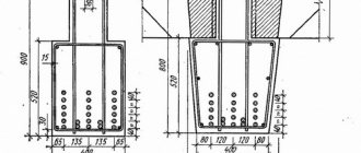
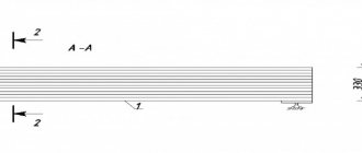
There are different sections of reinforced concrete crossbars, which are selected depending on their installation location and range. It varies from 250x200 mm to 400x600 mm. In this case, the width of the crossbar must correspond to the width of the adjacent column. In turn, the height of the object is calculated depending on the loads acting on the crossbar.
In the upper area of the crossbar there are closed protruding clamps, which, with the help of connecting elements, ensure its connection with the floor slab.
Prefabricated, prestressed crossbars, the price of which you can find out in our company, serve as ribs for a monolithic floor, the connection to them is carried out through the released fittings.
The tee, for which the floor most often serves as a shelf, is a cross-section of the crossbar. For further connection with the columns, grooves are made at the end of the crossbar. The reinforcement, which is passed through the body of the column and is located in the interface unit, is inserted into the grooves of the crossbars.
As mentioned earlier, different cross-section options for crossbars are possible; they are presented in the table below.
| b, mm | Transom width | |||||
| h, mm | 200 | 250 | 300 | 350 | 400 | |
| Transom height | 250 | |||||
| 300 | ||||||
| 350 | ||||||
| 400 | ||||||
| 450 | ||||||
| 500 | ||||||
| 550 | ||||||
| 600 | ||||||
| Length of the crossbar | Individual | |||||
You can purchase reinforced concrete crossbars for prefabricated monolithic frames from our representatives in Chelyabinsk, Tyumen, Noyabrsk (Yamalo-Nenets Autonomous Okrug), Surgut (Khanty-Mansiysk Autonomous Okrug).
Individual drawings for each object. TU 5825-002-75463284-2008, GOST 13015.
Legend:
| Full marking: PC LBH-T PC – crossbar L – indicator of the length of the crossbar (measured in dm) B – indicator of the width of the crossbar (measured in dm) H – indicator of the height of the crossbar (measured in dm) T – grade of concrete | Abbreviated marking: PN P – crossbar N – serial number of standard size |
Crossbar, length 5800 mm, cross-section 300x450 mm, made of heavy concrete, size number – 12.
"Chelyabinsk Prefabricated Monolithic Frame Plant" offers its customers to purchase reinforced concrete crossbars at affordable prices. See where our products are used.
Calculate delivery View videos View photographs of objects
Still have questions?
Contact us by phone: +7 (35152) 3-37-41 or in another way convenient for you.
Features of the manufacture of the crossbar:
Hot-dip galvanizingMetal crossbars withstand high loads for a long time during operation, so during their manufacture it is necessary to strictly adhere to the technology. The main characteristics of products are specified in GOST, including the order of reinforcement of structures. Such structural elements are most often manufactured at metal rolling or specialized metal structures factories. In order to use the product for its intended purpose and increase the reliability of the structure being built, the metal crossbar is made prestressed. For this purpose, hot-rolled structural steel of various grades is used, which is processed thermomechanically. Prestressed elements have high performance characteristics, so they are able to withstand high and long-term loads throughout the entire period of operation of the facility. All parts of the metal crossbar are made from the same grade of steel, and the quality and integrity of metal products is checked with a special ultrasonic flaw detector. In addition, after the manufacture or installation of metal crossbars, they are treated with anti-corrosion compounds (enamels or varnishes), since the metal is resistant to moisture.
SERVICE LIST
MOST DESIGN PROJECTS CONSISTE OF THREE MAIN STAGES: DESIGN, INTERIOR DESIGN AND 3D VISUALIZATION. THE FIRST OF THEM IS THE MOST IMPORTANT, BECAUSE BOTH THE OTHER TASKS AND THE VECTOR OF FUTURE WORK IN GENERAL DIRECTLY DEPEND ON IT. BUILDING DESIGN IS THE CREATION OF A PLAN AND STRUCTURE OF PREMISES. IN OTHER WORDS, AT THIS STAGE THE SQUARE AND SHAPE OF THE ROOMS, THE NUMBER AND LOCATION OF WINDOW AND DOOR OPENINGS ARE MADE.
THE DESIGN FIELD INVOLVES EMPLOYEES FROM DIFFERENT FIELDS: DESIGNERS, ARCHITECTS, DESIGNERS, SECURITY AND COMMUNICATIONS SPECIALISTS. IT IS IMPORTANT NOT ONLY TO DESIGN THE STRUCTURE BEAUTIFULLY, BUT ALSO TO ENSURE THE CORRECT CONDUCT OF ELECTRICITY, WATER, VENTILATION, AND NOT TO DAMAGE THE SUPPORTING STRUCTURES OF THE BUILDING. HOUSE DESIGN SERVICES SHOULD COMBINE INTERESTING DESIGN SOLUTIONS WHILE REMAINING RATIONAL FROM A TECHNICAL POINT OF VIEW.
IN ADDITION TO DESIGNING, WE ARE ENGAGED IN THE CREATION OF INTERIOR DESIGN AND ITS VISUALIZATION. THE LAST SERVICE IMPLIES THE CREATION OF A THREE-DIMENSIONAL DIGITAL MODEL OF THE HOUSING. THANKS TO MODERN TECHNOLOGIES, THE 3D MODEL LOOKS VERY REALISTIC, WHICH ALLOWS YOU TO DISPLAY THE FUTURE DESIGN AS ACCURATELY as possible.
IN THE “PRICES” SECTION YOU CAN READ THE LIST OF SERVICE PACKAGES AND THEIR COSTS. DEPENDING ON THE PACKAGE YOU CHOOSE, DIFFERENT WORK WILL BE DONE, FROM THE LAYOUT OF THE ROOMS TO THE CHOICE OF FURNITURE.
Installation of beams, trusses and crossbars
Foundation, strapping and crane beams, as well as crossbars with a clearance of up to 6 m, are installed using a two-legged sling using sling loops. In the absence of sling loops, girth rope slings or special slings with grips are used.
Beams, crossbars and trusses with a clearance of 12 m or more are installed using traverses.
The trusses are raised at two, three or four points to prevent the top chord from losing stability. This is especially important when lifting and erecting prestressed structures.
The elements are suspended from the crossbeam: using remote-controlled grippers from the crane cabin; for the hole in the element or in the girth of automatic slings.
Suspension devices when lifting trusses with a lantern are located outside the dimensions of the lantern.
Beams, crossbars and trusses are aligned to the design axes before removing the structures from the crane hook, according to the axial marks previously marked on the mounted elements and on the columns near the support units.
To temporarily secure parts in the absence or insufficient strength of fastenings on supports or fixing devices, screw spacers or temporary connections are used in accordance with the installation project, allowing additional verification of the structure or element. Elements of trusses and beams for large spans undergo enlarged assembly.
The overall assembly of all large structures is carried out at the manufacturing plants, oversized ones (hoppers, elements, trestles, trusses, beams, etc.) - on the assembly site directly at the installation site, in the area of operation of the main installation mechanisms or on specially designated areas.
Integrated assembly of composite prestressed structures consists of welding embedded metal parts of individual prestressed parts of structures in compliance with the required construction lifting of the structures as a whole. It is carried out on special stands, consisting of a conductor for bringing the mating sides of the semi-trusses together to the design position and forming a construction lift, roller supports for supporting the ends of the semi-trusses and brace clamps for fixing the position of the upper chord of the truss.
Block structures with reinforcement tension during assembly are enlarged by joint compression of individual blocks of structures that have reached their design strength. To do this, reinforcement (ready-made rods or bundles) is passed through the channels of pre-assembled blocks and tensioned to a given voltage using a hydraulic jack. Then the channels are filled under pressure with cement mortar to bond the reinforcement to the concrete and protect it from corrosion.
During the enlarged assembly of block prestressed structures, the following sequence of operations is observed:
- checking in each block (structure) the permeability of the longitudinal channels of the working fittings, the cleanliness and serviceability of the tees (nozzles) for injection of the solution, the presence, quality and correct location of embedded parts;
- installation of blocks on the stand with their straightening and fastening;
- inserting rod or beam reinforcement into longitudinal channels with preliminary tightening of the end fastenings, final straightening of the blocks, creation of a construction lift and checking the correct location and tightness of the rubber washers;
- filling the joints between blocks with mortar;
- welding of butt plates;
- tensioning the working reinforcement to the design value and securing it;
- filling the channels of working fittings with solution;
- checking the dimensions and appearance of structures;
- cutting off hinges and protruding ends of reinforcement, sealing end sockets.
Before installing the covering slabs, the beams and trusses are fastened together along the upper chord with rigid temporary struts.
Large-sized reinforced concrete slabs for covering industrial buildings are installed after installing each next beam or truss, securing them with connections provided in the design of the structures or in the design of installation work, alignment and final fastening of all underlying load-bearing structures.
Large-sized floor and coating slabs, depending on the load-carrying capacity of the mounting mechanism, are lifted in sizes of 1.5×6 m in 2-3 pieces. using a group traverse with semi-automatic slings, and for large sizes - 1 pc.
The order and direction of installation of slabs between trusses or roof beams, as well as between floor beams, must be indicated in the work design and ensure the stability of the erected structure, the safety of workers and the possibility of welding the slabs to the main structures of the project.
It is recommended to lay the slabs:
- along reinforced concrete roof trusses with a covering without a lantern: in single-span buildings - from one edge of the covering to the other;
- in gaps adjacent to previously installed or existing gaps;
- from the mounted covering to the free edge;
The installation locations of the first (beacon) slab must be marked in advance on each truss structure.
If the gaps between the embedded parts of slabs and rafter structures are more than 2 mm, steel spacers should be installed, welded to the embedded parts of the slab and roof truss. Where necessary, spacers should be placed under the two diagonally located corners of the slab, flush with the contour of the slab.
Each slab is welded to the truss structure with the seams specified in the project immediately after its installation, otherwise access to it will be difficult.
External and internal walls of one-story industrial buildings are erected from various materials.
Wall panels of one-story industrial buildings are installed by crane using traverses, securing slings to the hinges of the panel.
The order of installation of panels is established in the work project, and is linked to the installation of structures for filling window openings. External wall panels are aligned to the outer edges of the walls of the building.
Wall panels are mounted from lifting cradles or scaffolds located on the inner edge of the wall. Work on sealing seams is carried out from cradles and scaffolds located on the side of the outer wall.
See also:
- Burglary resistance of sectional doors
- Various types of fences, their advantages and disadvantages
Conclusion
Additional door locking mechanisms are a necessary and useful thing. They increase the security properties of the door, protecting it from forceful opening methods. But it is important that the vertical or horizontal locking is connected correctly. The weight of the rods should not exceed the maximum allowable for a particular lock model. Usually it is 250-400 grams. The rods should be connected to the locks using self-locking nuts or any other fastener that will not subsequently loosen due to vibration. There should be no misalignment to avoid additional load on the lock during operation. The holes for the crossbar and rods in the door frame should be slightly larger in diameter (2-3 mm). Locks with an additional vertical or horizontal drive connected should continue to work exactly the same as without it, that is, smoothly and clearly.
