The main material in the construction industry is concrete. It is used to produce structures and their elements of various types, purposes, in factories, at landfills, directly at construction sites, which form the supporting structure and appearance of structures. Regulatory documents establish practical requirements for the installation process of concrete and reinforced concrete products.
What types of reinforced concrete structures are there?
Products are divided into prefabricated, monolithic, prefabricated-monolithic. The first are factory samples, which are combined into a frame or connected to it by welding and subsequent concreting. The second ones are cast on objects whose frames will take increased loads (foundation slabs, swimming pools, self-supporting frames, etc.).
The latter rationally combine heterogeneous elements of the first and second types. Factory structures are equipped with conventional and prestressed reinforcement (increases resistance to bending loads). Monolithic products contain only conventional reinforcement cage.
Return to contents
Regulations
SNiP 3.03.01-87, which sets standards for all stages of installation of reinforced concrete structures, technologies and materials. GOST 10922-90, which establishes the general conditions for the formation of products from reinforcement and embedded parts for their welding in reinforced concrete structures. GOST 14098-91, standardizing types of structural design, geometric parameters of connections when welding embedded parts and reinforcement. The requirements of the listed documents are included in the project for the execution of work at construction sites (PPR).
Return to contents
How are the structures installed?
Installation of prefabricated concrete and reinforced concrete structures includes:
- intermediate storage and movement of products;
- installation of reinforced concrete products from prefabricated elements;
- working with concrete mixtures;
- reinforcement in monolithic structures;
- pouring and maintaining concrete until it reaches strength;
- concrete processing.
Return to contents
Warehousing and moving
Product storage scheme.
The placement of products on the construction site is carried out taking into account the installation sequence. Products are stacked in stacks (the permissible quantity is individual for a specific type) on pads about 3 cm high, located strictly one below the other, or in group cassettes. The frame components are placed in the installation area (the working radius of the crane's reach without changing its boom radius) of the crane. Changing the boom radius is allowed only for moving floor slabs. Moving of structural components is carried out only by lifting equipment.
The slings are attached to the mounting fittings in accordance with the drawings. Manual transfer of loads weighing up to 50 kg is allowed (dragging is prohibited) over a distance of up to 30 m. Before assembly, it is allowed to lay out similar components (columns, beams, etc.) on gaskets in order to inspect the condition of the valve outlets. Such structural outlets are protected from damage; attaching slings to them is unacceptable.
Lifting and lowering of loads is carried out with a static hover above the lift-off/installation point at a height of 300 mm. The spatial position of the products must correspond to the design position when installed in the building structure (examples - panels, columns, flights of stairs, etc.). To improve orientation in the air, use one or two guy ropes attached to them. Hardware at the construction site is placed in sorted form in a special room.
Return to contents
Concrete works
The components of concrete compositions are dosed by weight. The volume of water in the solution is a guideline for the volume of modifying additives that change the properties of concrete (frost resistance, plasticity, fluidity, hydrophobicity, etc.). The proportions of the components are determined in relation to all batches (grades) of cement and aggregates by testing samples for strength and mobility. It is not allowed to increase the workability of concrete by adding water to the mixed mixture. The requirements established by SNiP 3.03.01-87 for the formation of solutions are shown in Table 1.
Table 1.
Places of installation (forms), their seams and surfaces are cleaned of seasonal sedimentary moisture, dirt, debris, oil and grease stains, cement dust film, then washed under pressure and dried. The size of the aggregate grain fractions should not be more than 1/3 of the cross-sectional size of the seam at the narrowest point, and should not exceed 3/4 of the minimum distance between the reinforcing rods. Concrete is poured in layers. Vibrotamping is carried out by immersing the tool to a depth of 50 - 100 mm.
Its support on embedded parts, formwork and reinforcement is unacceptable. The step of movement along the surface is 1.5 times the radius of the equipment. Surface action models are rearranged with overlapping compaction areas by 100 mm. Subsequent layers of mortar are poured after the previous layer has gained strength to 1.5 MPa.
Return to contents
Concrete processing
After gaining strength, the concrete is covered with a cement screed 20–30 mm high, which is coated with a waterproofing compound. The reinforced concrete frame is subjected to the formation of technological holes and openings, anti-deformation joints (a set of strength indicators of 50% and above). It is preferable to use diamond cutting tools (vibration loads are excluded) with forced heat removal from the working area.
Return to contents
Reinforcement
Reinforcement of reinforced concrete structures.
Strengthening of structures is carried out by installing factory-made flat reinforcing meshes, which have longitudinal and transverse components, into the formwork. This reinforcement groups long rods and keeps the transverse ones from deforming. Volumetric connection of layers of structural reinforcement inside the formwork and working reinforcement of different products is carried out using binding wire, welding, screw couplings, crimp sleeves, etc. Before pouring, the quality of metal installation is checked, the form is freed from debris and scale.
The reinforcing structure must have a protective layer of concrete 20–30 mm high on all sides. Pouring the solution is accompanied by compaction using bayonet and vibratory rammer. The percentage of reinforcement (the ratio of the sum of the cross-sectional areas of the reinforcing metal to the cross-sectional area of the structure) of the lower columns of the building is set to not less than 2.01%, the upper - 0.79%. Metal can fill a concrete structure with no more than 0.1%.
Return to contents
Filling and care
In the warm season, concrete is protected from uneven drying with moisture-absorbing materials, covered with plastic film, and protected from direct heating by the sun. 10 - 14 hours after pouring, the concrete is irrigated with water every 3 - 4 hours for 7 - 14 days. After 10–14 days, the side formwork is removed, but irrigation of the product continues. In low temperature conditions, the filling can be heated with special equipment. Installation work on cast components begins after reaching 70% of brand strength (for conventional compositions - 28 days).
Return to contents
Construction of concrete and reinforced concrete monolithic structures
Specialists carry out work on the design and installation of monolithic reinforced concrete and concrete structures in Moscow and regions of Russia.
At affordable prices, we will erect buildings and structures, using technologies for installing monolithic concrete and reinforced concrete structures, with the arrangement of a ventilated facade, in compliance with SNIPs and safety regulations, and quality control of work at all stages of construction.
Modern monolithic structures, from a financial point of view, are the most profitable option for constructing buildings for the customer.
We provide the following types of services for the installation of concrete and reinforced concrete structures:
- installation of monolithic concrete and reinforced concrete structures, including stairs, hanging gardens, skylights;
- reinforcement works;
- formwork work.
The use of the method of constructing structures using monolithic structures allows you to quickly construct a building of any complexity, shape and number of storeys. The production of monolithic structures is carried out by the company’s specialists from a concrete-containing mixture poured into special forms - formwork. Also, using enclosing structures, a rigid frame is created.
The advantages of constructing monolithic concrete and reinforced concrete building structures over other types of construction are:
- durability and seismic resistance;
- lightness of construction and reduced material consumption of the foundation;
- seamless design, smooth walls and ceilings;
- possibility of free planning;
- high thermal conductivity and soundproofing;
- short construction period and low cost.
Design and calculation of monolithic reinforced concrete structures, preparation of drawings and estimates, execution and coordination with the customer and regulatory authorities are carried out exactly on time with the provision of guarantees for the construction of monolithic structures and their subsequent maintenance.
When installing monolithic structures, the following stages are distinguished:
- pit preparation;
- installation of reinforcement frame and construction formwork;
- preparation of concrete mixture;
- concreting of monolithic structures;
- warming up if necessary (during the cold season);
- providing concrete care – finishing;
- removal of construction formwork.
When carrying out all work on the construction of monolithic concrete structures, we strictly adhere to the above sequence of installation of concrete monolithic structures.
Monolithic concrete structures erected by our specialists are different:
- with load-bearing longitudinal and transverse walls;
- with floors on load-bearing columns;
- stationary, lifting and self-climbing, climbing formwork systems;
- beam and frame formwork made of various materials: wood, plastic, steel, aluminum;
- formwork for walls, ceilings and columns.
Find out the cost of erecting monolithic reinforced concrete and concrete structures from the company’s specialists. We will provide all the necessary consultations on the project, when drawing up technical maps, we offer options, perform technological calculations, and use technologies to reduce the consumption of concrete and reinforcement.
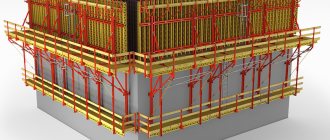
Features of installation of prefabricated products
Laying tie (spacer) (a) and row (b) floor slabs.
Installation of reinforced concrete structures is carried out in spans, ensuring the formation of a strong structure of the structure frames. Assembly is carried out according to technological maps in compliance with the requirements of the project. A new tier of structural components is installed after the frame has been secured and the monolithic reinforced concrete structures (inserts) have reached 70% strength. Structural units are inspected for the absence of cracks, chips, cavities, unprotected reinforcement, etc. Overall dimensions, the presence of embedded parts, holes and outlets of reinforcement are also checked.
The columns are inserted into the glasses immediately in the design position on a rigid leveling solution (it is unacceptable to place them on metal). Its thickness is determined by the height marks of the products. The slings are removed from the columns only after they are finally secured in the glass with wedge-shaped inserts (braces, conductors). Welded columns, wall panels, etc. are not loaded until the monolithic concrete gains brand strength; they are ensured of reliable fixation by a set of installation equipment. If necessary, the reinforced concrete column is returned to a vertical position (within tolerances) using jacks.
Before embedding, the reinforcement is protected from corrosion. The solution in the nests of the glasses is vibrated. Loaded joints are formed with concrete of higher grades (fast-hardening, expanding from M400 and higher) than in the project. The liners are removed after the monolithic structure has reached the established strength. The PPR for all joints indicates how they will be sealed (caulked), whether it will be a mortar or a monolith, and the types of reinforcement to be joined are listed.
Crossbars, columns, beams and floor slabs are attached by welding to the embedded plates. Floor slabs are laid on a mortar no higher than 2 cm; the overall plane of the slabs is checked from the ceiling. The first plate is welded at 4 points, subsequent plates at 3 points.
Crossbars, rafter beams, intercolumn slabs are laid without mortar. Ventilation blocks are hermetically sealed with mortar in horizontal seams. Welds must not be struck at temperatures: minus 25 degrees and below for steel with a yield limit of up to 390 MPa, zero degrees - with a yield limit of 390 MPa or more.
Return to contents
GOSSTROY USSR
CENTRAL RESEARCH AND DESIGN AND EXPERIMENTAL INSTITUTE OF ORGANIZATION, MECHANIZATION AND TECHNICAL ASSISTANCE FOR CONSTRUCTION
(TsNIIOMTP)
TECHNOLOGICAL MAP FOR THE CONSTRUCTION OF MONOLITHIC STRUCTURES OF TANK STRUCTURES USING CONCRETE PUMPS AND VIBRATION-FREE CONCRETE PLATING TECHNOLOGY
MOSCOW - 1986
Recommended for publication by the decision of the section of construction technology of the Scientific and Technical Council of the TsNIIOMTP Gosstroy of the USSR.
The technology for constructing monolithic walls of cylindrical silos in sliding formwork using concrete pumps and a vibration-free concreting method is considered.
Employees of TsNIIOMTP took part in the development of the technological map: Doctor of Technical Sciences. K.I. Bashlay, Ph.D. N.I. Evdokimov, Ph.D. E.P. Mazov, A.I. Petrushina, Ph.D. Yu.B. Chirkov, V.P. Churakov, Yu.A. Yarymov.
The work is intended for research, educational and construction organizations.
CONTENT
| 1 area of use. 1 2. Organization and technology of the construction process. 1 3. Technical and economic indicators. 5 4. Material and technical resources... 5 |
1.1. The technological map provides for the construction of monolithic walls of cylindrical silos in sliding formwork using concrete pumps and cast concrete mixtures using a combined (load-pressure) method. The representative object is a warehouse for bulk storage of granulated sugar.
1.2. Object characteristics
The warehouse consists of three free-standing cylindrical silos, one of which is connected to a 10-story rectangular elevator tower.
Main parameters (in mm):
internal diameter of silos - 24500;
height from the floor of the silo floor to the cornice of the cylindrical part - 33000;
wall thickness - 250.
2.1. Before starting work on the construction of walls there must be:
formwork panels, reinforcement cages, meshes and bundles, embedded parts were delivered and laid at storage sites;
the necessary equipment, equipment and tools are prepared for work;
tower crane KB-160.2 was installed;
a concrete pumping unit SB-161 or SB-165, a concrete pipeline, a distribution boom support and a boom SB-136 were installed.
2.2. Installation and dismantling of formwork, supply of reinforcement cages and meshes, reinforcement beams and embedded parts are carried out using a tower crane.
2.3. After the construction of the outer walls, the installation of the over-silo gallery and the installation of the warehouse covering, the reinforcement bundles are tensioned in the warehouse walls. Tensioning begins at +3.40 at the same time with three reinforcement beams located in one tier along the contour of the warehouse walls. After tensioning and anchoring the ends of the bundles, the channels are injected and the end surfaces are sealed with cement mortar.
2.4. The concrete pump and steel support in the central part of the cylindrical silo are installed on a planned horizontal base. The vertical part of the concrete pipeline is attached to the support. The stability of the steel support from inventory steel sections is ensured using temporary steel fastenings.
2.5. Concreting of silo walls with cast concrete mixtures is carried out using a concrete pumping unit SB-161 (SB-165) and a distribution boom SB-136.
The cast concrete mixture is transported in concrete mixer trucks, which eliminates its stratification, loss of homogeneity, and leakage of cement laitance.
To maintain the specified mobility of the cast concrete mixture, the duration of its supply to the formwork (counting from the moment of unloading) should not be more than 20 - 30 minutes.
First, two to three layers of cast concrete mixture are placed in a fixed formwork for 2.5 - 3.5 hours at half the height of the formwork. Moreover, each subsequent layer is laid after the completion of laying the previous one along the entire contour of the formwork. Further filling of the formwork with concrete mixture is carried out if concrete does not flow out from under the formwork panels. When concreting, the following conditions must be met:
the upper level of the laid mixture should not be lower than 50 mm from the top of the formwork panel;
each subsequent layer of concrete mixture is placed in the formwork before the previous layer begins to set;
if there are forced breaks in concreting for more than 2 hours, before the break begins, the formwork should be filled to the top with concrete mixture; It is also impossible to interrupt concreting without finishing laying the started layer along the entire perimeter of the concreting block.
During the break, the speed of lifting the formwork is slowed down enough to prevent adhesion of the concrete to the formwork. By the time the lift is completed, the distance between the working floor and the horizon of the laid concrete should not exceed 500 mm.
Preventing the adhesion of the formwork to concrete is achieved by periodically raising and lowering it using hydraulic jacks to a small height (several centimeters).
Through holes on the outside of the walls are closed with removable plugs to prevent leakage of the cast concrete mixture.
2.6. In accordance with SNiP III-15-76 “Rules for the production and acceptance of work. Concrete and reinforced concrete structures are monolithic” when maintaining the laid concrete in the initial period of its hardening, it is necessary to maintain a favorable temperature and humidity regime. Significant temperature-shrinkage deformations and mechanical damage are unacceptable.
The surface of the laid concrete must be protected from direct sunlight and wind. The most common type of concrete maintenance is continuous moisture maintenance, consisting of an initial and subsequent period. In the initial period, it is planned to protect freshly laid concrete from direct sunlight and wind by carefully covering it with moisture-proof (for the side surfaces) and moisture-absorbing materials, installing curtains made of wet tarpaulin, burlap or other similar material), followed by regular watering of the laid concrete.
Quality control of the concrete mixture and sampling is carried out in accordance with GOST 10180-78. The following are subject to control: the accuracy of dosage of materials in the production of concrete mixture, its pumpability and workability, as well as the physical and mechanical characteristics of concrete.
In hot weather, the concrete pipeline must be protected from exposure to sunlight by painting it white or wrapping it in thermally insulating shells made of mineral wool and fiberglass.
The maximum duration of breaks when supplying concrete mixture should not exceed 15 minutes. The permissible temperature of the concrete mixture entering the concrete pump is no more than +30 °C.
It is prohibited to restore the mobility of the concrete mixture to the specified consistency by adding water to the concrete pump hopper.
Immediately before starting concreting, it is necessary to test the operation of the concrete pump at idle. Before receiving the concrete mixture, 1 m3 of “starting solution” of a 1:1 composition (cement:sand) with a mobility of 15 - 18 cm should be fed into the concrete pump hopper along the StroyTsNIL cone.
Turning on the concrete pump and supplying the cast concrete mixture after the “starting solution” should be carried out at first speed until a confirmation signal is received from the concrete workers that the mixture is ready to be accepted into the formwork. After this, the feed rate can be increased in accordance with the required concreting intensity. The most favorable delivery mode is to operate the concrete pump at first and second speeds.
During the pumping process, it is necessary to ensure that there is at least 250 liters of concrete mixture in the concrete pump hopper at all times (the level of the concrete mixture should be 7 - 10 cm above the mixer blades).
Forced breaks in the supply of cast concrete mixture should not exceed 30 - 40 minutes. At the same time, at least 250 liters of concrete mixture must also remain in the pump hopper for periodic pumping and reversing. During long breaks, the concrete mixture must be pumped out, and the pipeline, hopper and pump cylinders must be washed with water.
During the pumping process, it is recommended to constantly stimulate the cast concrete mixture in the pump hopper using a mixer.
Cleaning and flushing of the concrete pump transport system is carried out at the end of each shift, and in the case of continuous concreting - after completion of work.
Washing concrete mixer trucks is necessary when the duration of the period from the end of unloading the concrete mixture into the pump hopper to the reloading of the concrete mixer truck at the concrete plant exceeds 45 minutes. There should also be a permanent tanker with water on site for cleaning equipment.
When a plug appears in the concrete pipe, it is necessary to switch the machine to pumping mode and pump out the concrete mixture from the concrete pipe into the receiving hopper in 1 - 2 strokes of the piston. If it is not possible to remove the plug by pumping, it is necessary to turn off the pump and, by disconnecting the corresponding link of the concrete pipeline, remove the plug. Plugs mainly form in the exit area of the gate body, in the adapter, elbows and the final distribution hose. Before opening the concrete pipeline, it is necessary to minimize the pressure in it by back-suction.
2.7. When carrying out work on concreting walls in sliding formwork, using a concrete pump, it is necessary to strictly observe the safety rules set out in the current regulatory and instructional documents and in particular: SNiP III-4-80 “Safety in construction”; “Guidelines for laying concrete mixtures using concrete pumping units.”
Before the start of work, it is necessary to instruct and train workers in safe labor practices when producing concrete work. Work with the concrete pump must be carried out in the presence of an engineer and technical worker responsible for the safe conduct of work at the construction site.
It is prohibited to be in the danger zone near the concrete pump and within the radius of rotation of the boom.
Only specially trained drivers - operators with certificates - are allowed to operate the concrete pump and distribution boom.
When operating a concrete pumping system with a distribution boom, the following must be taken into account:
operation of the boom is not allowed until the concrete pump and distribution boom are installed on stable supports;
the distribution boom can be used when the wind strength and speed are not higher than those specified in the passport - instructions for its use;
the boom rotation speed should not exceed 0.5 rpm;
It is prohibited to use an end hose on a distribution boom with a length greater than that indicated in the passport - operating instructions.
When performing work at night, it is necessary to equip the distribution boom with an external light source to illuminate the concrete laying site.
The control system of a concrete pumping installation must provide electrical audio communication between the boom operator and the concrete pump mechanic.
2.8. Quality control of work performed
| Works subject to control | Control procedure | ||||
| producer of the work | master | Compound | Methods | Time | Involved services |
| 1 | 2 | 3 | 4 | 5 | 6 |
| Preparatory | — | The quality of the formwork. Compliance with the design of the base level | Visually; level | Before concreting | Surveyor |
| Concreting walls | — | Checking the position of reinforcement cages and embedded parts | Visually | During the concreting process | Surveyor |
| Surface quality, presence of holes and compliance with the design | Visually; steel meter, level | During the concreting process | Surveyor | ||
| Strength of concrete, its homogeneity, presence of pores, cracks | Ultrasound device UKB; visually; dice test | After stripping | Laboratory | ||
| — | Preparatory | Quality of the base (cleaning from dirt, washing, etc.) | Visually | Before concreting | — |
| — | Laying concrete mixture | Quality of the concrete mixture (workability, homogeneity) | Along the cone StroyTsNIIL | Before installation into the structure | Laboratory |
| Wet sieving method | Same | Same | |||
| The quality of the surface, the walls released from under the formwork, the verticality of the walls, the strength of concrete in structures | Visually; level; dice test | During the concreting process | Laboratory | ||
| — | Curing | Compliance with humidity and temperature conditions | Visually; thermometer | During hardening | — |
Volume of concrete work, m3 633
Labor costs for the construction of silo walls, man-days. 1059.01
The same, per 1 m3 of concrete, person-hour 13.72
Labor costs for laying the entire volume of concrete, man-days. 88.38
The same, per 1 m3, person-hour 1.27
Output per worker per shift, m3
during the construction of silo walls 0.59
when laying concrete mixture 7.16
4.1. Requirement for basic materials
| Name | Brand | Unit change | Qty |
| Concrete | M300 | m3 | 646 |
| Cement mortar | M75 | m3 | 6,5 |
| Armature | — | T | 70,5 |
| Embedded parts | — | T | 21 |
| Reinforcement beams | — | T | 30,3 |
4.2. Need for machines, equipment, tools, supplies and fixtures
| Name, brand, | GOST | Qty | Characteristic |
| 1 | 2 | 3 | 4 |
| Assembly tower crane KB-160.2 | — | 1 | Load capacity 5 - 8 t; boom radius 25 m |
| Concrete mixer truck SB-91-1 | — | 4 | Mixing drum volume 3.5 m3 |
| Concrete pumping unit SB-161 (SB-165) | — | 1 | Capacity 5 - 65 (5 - 20) m3/h |
| Distribution boom SB-136 | — | 1 | Boom radius 18 m |
| Two-leg sling | GOST 25573-82 | 2 | Load capacity 4 t |
| Bunker | GOST 21807-76 | 1 | Capacity 1 m3 of concrete mixture |
| Construction shovel LR | GOST 3620-76 | 4 | — |
| Pick-up shovel LP-2 | GOST 3620-76 | 4 | — |
| Control rack | — | 4 | — |
| End cutters K-200 | GOST 7282-75 | 3 | — |
| Carpenter's hammer MPL | GOST 11042-83 | 4 | — |
| Trowel KSh | GOST 9533-81 | 2 | — |
| Level NV-1 | GOST 10528-76 | 1 | — |
| Steel construction plumb OT-400 | GOST 7948-80 | 2 | — |
| Construction level US-300 | GOST 9416-83 | 2 | — |
| Steel measuring tape RS-20 | GOST 7502-80 | 2 | — |
| Safety belt | GOST 12.4.-089-80 | 17 | — |
| Construction helmet | GOST 12.4.-087-80 | 17 | — |
CALCULATION OF THE NUMBER OF CONCRETE MIXERS REQUIRED FOR UNINTERRUPTED DELIVERY OF CONCRETE MIXTURE
The required number of concrete mixer trucks is determined by the formula:
where T1 is the duration of loading and unloading of the concrete mixer truck - 15 minutes;
duration of transportation of the mixture from the ready-mixed concrete plant to the concrete pump (including the return journey), min.
L — transportation range — 10 km,
U - average speed of the concrete mixer truck - 20 km/h,
— interval for delivery of concrete mixture to the concrete pump, min;
q — useful volume of the mixing drum of a concrete mixer truck — 3.5 m3,
Q - total volume of monolithic concrete laid in the structure - 633 m3;
Tch is the volume of the mixture to be laid with a concrete pump capacity of 19.35 m3/h.
Then
Four concrete mixer trucks are accepted.
Notes: 1. Fractional numbers obtained during calculations are always rounded to a larger number.
2. The number of concrete mixer trucks cannot be less than two.
CALCULATION OF LABOR COSTS FOR INSTALLATION OF SLIDING FORMWORK FOR SILOS WALLS
| Rationale | Name of works | Unit change | Scope of work | Standard time per unit. Meas., person-hours (machine-hours) | Labor costs for the entire volume of work, person-days. (machine-shift) | Price per unit change, rub.-kop. | Cost of labor costs for the entire scope of work, rubles-kopecks. |
| 1 | 2 | 3 | 4 | 5 | 6 | 7 | 8 |
| Collection 8 TsNIIA | Geodetic layout of wall axes | 1m | 51 | 0,18 | 1,12 | 0-10,8 | 5-51 |
| ENiR 1979, No. 1-6, table. 2, clause 26a, K = 1.12 to the driver’s rate | Supply by crane to the installation site of metal sliding formwork structures, jacking frames, jacking rods, hydraulic jacks | 100 t | 0,38 | 0,38 (19,00) | 1,76 (0,88) | 21-00 (13-30) | 7-98 (5-05) |
| ENiR 1980, § 4-1-43b, tab. 2, item 1, K = 0.8 | Rimming and installation of internal wall formwork with fastening of brackets and scaffold hangers | 1 t | 10 | 15,20 | 18,54 | 8-70,4 | 87-04 |
| ENiR 1980, § 4-1-45, paragraph 1 | Construction of an internal working floor with fencing and suspended scaffolding | m2 | 160 | 1,10 | 21,46 | 0-64,9 | 103-80 |
| ENiR 1980, § 4-1-48, paragraph 2 | Installation of fittings | 1 t | 13 | 40,00 | 63,40 | 26-54 | 345-02 |
| ENiR 1979, § 1-6, tab. 2, paragraph 28a; K = 1.12 to the driver’s rate | Feeding reinforcement beams by crane | 100 t | 0,03 | 19,60 (9,80) | 0,07 (0,04) | 9-66 (6-86,6) | 0-29 (0-21) |
| ENiR 1980, § 4-1-34, paragraph 12d | Installation of reinforcement beams | 1 t | 3 | 17,50 | 6,40 | 11-23 | 33-69 |
| ENiR 1980, § 4-1-43b, tab. 2, item 1, K = 0.8 | Assembly and installation of external wall formwork with fastening of brackets and scaffold hangers | 1 t | 12 | 15,20 | 22,24 | 8-70,4 | 104-40 |
| ENiR 1980, § 4-1-45, paragraph 1 | Construction of an external working floor with fencing and suspended scaffolding | 1 m2 | 169 | 1,10 | 22,68 | 0-64,9 | 109-70 |
| ENiR 1980, § 4-1-45, paragraph 1 | Installation of jack frames | 1 frame | 42 | 1,75 | 8,96 | 1-03 | 43-40 |
| ENiR 1980, § 4-1-44A, tab. 1, paragraph 6 | Installation of hydraulic single-cylinder jacks with their fastening to the frame | 1 jack | 42 | 0,47 | 2,41 | 0-27,7 | 11-63 |
| ENiR 1980, § 4-1-44a, tab. 1, paragraph 7 | Installation of jack rods | 1 rod | 42 | 0,115 | 0,59 | 0-06,8 | 2-86 |
| ENiR 1980, § 4-1-47, paragraph 1 | Installing plugs for jacking rods | 1 stopper | 42 | 0,27 | 1,38 | 0-19 | 7-98 |
| ENiR 1973, § 5-1-6, pp. 1.2g | Installation and adjustment of internal rods | 1 element | 85 | 0,41 | 4,25 | 0-26,7 | 22-70 |
| 1 t | 0,55 | 3,80 | 0,25 | 2-48 | 1-36 | ||
| ENiR 1980, § 4-1-44a, tab. 1, paragraph 12, K = 1.1 | Installation of hydraulic distribution network | 1 m pipeline | 200 | 0,50 | 12,20 | 0-30,1 | 60-20 |
| ENiR 1980, § 4-1-44a, tab. 1, paragraph 13, K = 1.1 | Connecting hydraulic jacks to the pipeline with installation of supply pipes | 1 tube | 84 | 0,17 | 1,69 | 0-10,3 | 8-69 |
| ENiR 1980, § 4-1-44a, tab. 1, paragraph 10 | Installation of verticality control devices | 1 device | 4 | 8,70 | 4,24 | 5-13 | 20-52 |
| ENiR 1980, §4-1-46b, tab. 2, item 1 | Installation of a pump distribution station | 1 station | 2 | 2,70 | 0,66 | 1-69 | 3,38 |
| Timing data | Inspection of jacks | 1 jack | 42 | 1,62 | 8,30 | 1-18 | 49-50 |
| ENiR 1974., § 9-1-8b, table. 2, pp. 2 and 3 (applicable) | Hydraulic system inspection | 100 m pipeline | 2 | 4,30 | 1,06 | 3-10 | 6-20 |
| ENiR 1974, § 23-1-6, paragraph 2a | Installation of electrical power and lighting networks | 100 m wire | 0,81 | 9,50 | 0,94 | 5-31 | 4-30 |
| ENiR 1974, § 6-1-31, paragraph 2a | Construction of stepladders from ready-made panels | 1m | 3,5 | 0,50 | 0,21 | 0-25,9 | 0-91 |
| ENiR 1974, § 8-24k, tab. 13, paragraph 3a | Lubricating formwork panels | 100 m2 surface | 1,62 | 5,50 | 1,09 | 2-71 | 4-40 |
| Total | 205,90 | 1045-46 | |||||
calculation of labor costs for the construction of the 1st tier of silo walls
| Rationale | Name of works | Unit change | Scope of work | Standard time per unit. Meas., person-hours (machine-hours) | Labor costs for the entire volume of work, person-days. (machine-shift) | Price per unit change, rub.-kop. | Cost of labor costs for the entire scope of work, rubles-kopecks. | |
| 1 | 2 | 3 | 4 | 5 | 6 | 7 | 8 | |
| ENiR 1973, § 5-1-6, paragraph (applicable) | Installation of four inventory sections of the distribution boom support with temporary fastening | 1 element | 2,19 | 9-71 | ||||
| 1 t | ||||||||
| ENiR 1973, § 35-21, paragraph 14 (applicable) | Distributing Boom Installation | 1 PC. | 1 | 30,00 | 3,66 | 18-86 | 18-86 | |
| ENiR 1980, § 4-1-36, tab. 4, paragraph 1a | Installation of concrete pipeline | m concrete pipeline | 15-horizontal section | 0,32 | 0,59 | 0-17,9 | 2-69 | |
| The same, K = 1.7 | 17-vertical section | 0,54 | 1,12 | 0-30,4 | 5-17 | |||
| ENiR 1979, § 1-6, tab. 2, clause 26a, K = 1.12 to the driver’s rate | Feeding reinforcing bars by crane | 100 t | 0,105 | 38,00 (19,00) | 0,48 (0,24) | 18-73 (13-30) | 1-97 (1-40) | |
| ENiR 1979, § 1-6, tab. 2, clause 32a, K = 1.12 to the driver’s rate | Supply of embedded parts by crane | 100 lifts | 0,007 | 14,00 (7,00) | 0,02 (0,01) | 6-90 (4-91) | 0-05 (0-03) | |
| ENiR 1979, No. 1-5, table. 2 clause 26a, K = 1.12 to the driver’s rate | Feeding jacking rods by crane | 100 t | 0,013 | 38,00 (19,00) | 0,05 (0,03) | 18-73 (13-30) | 0-24 (0-17) | |
| ENiR 1979, § 1-6, tab. 2, clause 28a, K = 1.12 to the driver’s rate | Feeding reinforcement beams by crane | 100 t | 0,071 | 19,60 (9,80) | 0,17 (0,09) | 9-66 (6-87) | 0-69 (0-49) | |
| ENiR 1980, § 4-1-31, paragraph 2b | Installation of embedded parts | 1 piece | 178 | 0,40 | 8,68 | 0-23,6 | 42-01 | |
| ENiR 1980, § 4-1-48, paragraph 2 | Extension of reinforcing bars | 1 t | 10,50 | 40,00 | 114,63 | 26-54 | 623-69 | |
| ENiR 1983, § 4-1-36b, tab. 5 (applicable) | Laying concrete mixture into silo walls | Receiving concrete mixture into the receiving hopper of a concrete pump | 1 m3 | 214 | 0,115 | 3,00 | 0-05,7 | 12-03 |
| According to calculated data | Supplying concrete mixture to the laying site | 1 m3 | 214 | 1,00 | 26,16 | 0-66 | 141-24 | |
| ENiR 1980, § 4-1-44a, tab. 2, paragraph 7 | Installation of jack rods | 1 rod | 168 | 0,115 | 2,36 | 0-06,8 | 11-42 | |
| ENiR 1980, § 4-1-48, paragraph 7, 8 | Lifting sliding formwork with hydraulic jacks | 1 m rise | 8 | 21,16 | 20,64 | 13-24 | 105-92 | |
| ENiR 1980, § 4-1-48, paragraph 9 | Finishing the concrete surface with sealing failures | 1 m2 surface | 1503 | 0,18 | 33,00 | 0-10 | 150-30 | |
| ENR 1980, § 4-1-34, paragraph 12e (applicable) | Laying reinforcement beams | T | 7,10 | 14,00 | 12,12 | 8-98 | 63-76 | |
| ENiR 1980, § 4-1-42, paragraph 7 | Watering the concrete mixture with water | 100 m2 | 15,03 | 0,15 | 0,27 | 0-07,4 | 1-11 | |
| ENiR 1973, paragraph 14 (applicable) | Dismantling the distribution boom | PC. | 1 | 18,50 | 2,26 | 11-63 | 11-63 | |
| Total | 231,37 (0,37) | 1211-49 (2-09) | ||||||
CALCULATION OF LABOR COSTS FOR THE CONSTRUCTION OF THE 2nd LAYER OF SILOS WALLS
| Rationale | Name of works | Unit change | Scope of work | Standard time per unit. Meas., person-hours (machine-hours) | Labor costs for the entire volume of work, person-days. (machine-shift) | Price per unit change, rub.-kop. | Cost of labor costs for the entire scope of work, rubles-kopecks. | |
| 1 | 2 | 3 | 4 | 5 | 6 | 7 | 8 | |
| ENiR 1973, § 5-1-6, paragraph (applicable) | Installation of three inventory sections of the distribution boom support with temporary fastening | 1 element | 1,47 | 7-87 | ||||
| 1 t | 1,47 | |||||||
| ENiR 1973, § 35-21, paragraph 4 | Distributing Boom Installation | PC. | 1 | 30,00 | 3,66 | 18-86 | 18-86 | |
| ENiR 1980, § 4-1-36, tab. 4, paragraph 1a, K = 1.1; K = 1.04 | Installation of concrete pipeline | m concrete pipeline | 9 | 0,56 | 0,61 | 0-31,6 | 2-84 | |
| ENiR 1979, § 1-6, tab. 2, clause 26a, b, K = 1.12 to the driver’s rate | Feeding reinforcing bars by crane | 100 t | 0,235 | 43,80 (21,90) | 1,26 (0,63) | 21-59 (15-40) | 5-07 (3-62) | |
| ENiR 1979, § 1-6, tab. 2, clause 32a and b, K = 1.12 to the driver’s rate | Supply of embedded parts by crane | 100 lifts | 0,007 | 16,40 (8,20) | 0,02 (0,01) | 8-08 (5-13) | 0-06 (0-04) | |
| ENiR 1979, § 1-6, tab. 2, clause 26a and b, K = 1.12 to the driver’s rate | Feeding jacking rods by crane | 100 t | 0,014 | 43,80 (21,90) | 0,08 (0,04) | 21-59 (15-40) | 0-30 (0-22) | |
| ENiR 1979, § 1-6, tab. 2, clause 28a and b, K = 1.12 to the driver’s rate | Feeding reinforcement beams by crane | 100 t | 0,101 | 22,50 (11,25) | 0,28 (0,14) | 11-09 (7-86) | 1-12 (0-79) | |
| ENiR 1980, § 4-1-31, paragraph 2b, K = 1.04 | Installation of embedded parts | 1 piece | 176 | 0,42 | 9,01 | 0-24,5 | 43-12 | |
| ENiR 1980, § 4-1-48, paragraph 2, K = 1.04 | Extension of reinforcing bars | 1 t | 23,50 | 41,60 | 119,22 | 26-60 | 625-10 | |
| ENiR 1980, § 4-1-36b, tab. 5 (applicable) | Laying concrete mixture into silo walls | Receiving concrete mixture into the concrete pump hopper | 1 m3 | 214 | 0,115 | 3,00 | 0-05,7 | 12-20 |
| According to calculated data | Supplying the concrete mixture with a concrete pump to the laying site | 1,03 | 26,84 | 0-68 | 145-48 | |||
| ENiR 1980, § 4-1-44a, tab. 2, item 7, K = 1.04 | Installation of jack rods | 1 rod | 210 | 0,12 | 3,07 | 0-07,1 | 14-91 | |
| ENiR 1980, § 4-1-48, paragraphs 7 and 8, K = 1.04 | Lifting sliding formwork with hydraulic jacks | m rise | 10 | 22,01 | 26,84 | 13-77 | 137-70 | |
| ENiR 1980, § 4-1-48, paragraph 9, K = 1.04 | Surface finishing with breakdown sealing | m2 surface | 1503 | 0,19 | 34,83 | 0-10,4 | 156-31 | |
| ENiR 1980, § 4-1-34, paragraph 12e, K = 1.04 (applicable) | Laying reinforcement beams | 1 t | 10,10 | 14,56 | 17,93 | 9-34 | 94-33 | |
| ENiR 1980, § 4-1-42, paragraph 7, K = 1.04 | Watering the concrete mixture with water | 100 m2 | 15,03 | 0,16 | 0,29 | 0-07,7 | 1-16 | |
| ENiR 1973, § 35-22, paragraph 14 (applicable) | Dismantling the distribution boom | PC. | 1 | 18,50 | 2,26 | 11-63 | 11-63 | |
| Total: | 250,67 (0,82) | 1278-06 (4-67) | ||||||
CALCULATION OF LABOR COSTS FOR THE CONSTRUCTION OF THE 3rd LAYER OF SILOS WALLS
| Rationale | Name of works | Unit change | Scope of work | Standard time per unit. Meas., person-hours (machine-hours) | Labor costs for the entire volume of work, person-days. (machine-shift) | Price per unit change, rub.-kop. | Cost of labor costs for the entire scope of work, rubles-kopecks. | |
| 1 | 2 | 3 | 4 | 5 | 6 | 7 | 8 | |
| ENiR 1973, § 5-1-6, etc. and (as applicable) | Installation of three inventory sections of the distribution boom support with temporary fastening | 1 element | 1,47 | 7-87 | ||||
| 1 t | ||||||||
| ENiR 1973, § 35-21, paragraph 14 (applicable) | Distributing Boom Installation | PC. | 1 | 30,00 | 3,66 | 18-86 | 18-86 | |
| ENiR 1980, § 4-1-36, tab. 4, paragraph 1a, K = 1.7 and K = 1.07 | Installation of concrete pipeline | m concrete pipeline | 9 | 0,58 | 0,64 | 0-32,5 | 2-88 | |
| ENiR 1979, § 1-6, tab. 2, clause 26a and b, K = 1.12 to the driver’s rate | Feeding reinforcing bars by crane | 100 t | 0,235 | 49,60 (24,80) | 1,42 (0,71) | 24-45 (17-36) | 5-75 (4-08) | |
| ENiR 1979, § 1-6, tab. 2, clause 32a and b, K = 1.12 to the driver’s rate | Supply of embedded parts by crane | 100 lifts | 0,007 | 18,80 (9,40) | 0,02 (0,01) | 9-26 (6-58,6) | 0-06 (0-05) | |
| ENiR 1979, § 1-6, tab. 2, clause 26a and b, K = 1.12 to the driver’s rate | Feeding jacking rods by crane | 100 t | 0,014 | 49,60 (24,80) | 0,08 (0,04) | 24-45 (17-36) | 0-34 (0-24) | |
| ENiR 1979, § 1-6, tab. 2, clause 28a and b, K = 1.12, to the driver’s price | Feeding reinforcement beams by crane | 100 t | 0,101 | 25,40 (12,70) | 3,10 (1,55) | 12-52 (8-89,5) | 1-26 (0-90) | |
| ENiR 1980, § 4-1-31, paragraph 2b, K = 1.07 | Installation of embedded parts | 1 piece | 176 | 0,43 | 9,23 | 0-25,3 | 44-53 | |
| ENiR 1980, § 4-1-48, paragraph 2, K = 1.07 | Extension of reinforcing bars | 1 t | 23,50 | 42,80 | 122,66 | 28-39,8 | 667-36 | |
| ENiR 1980, § 4-1-36b, tab. 5 (applicable) | Laying concrete mixture into silo walls | Receiving concrete mixture into the concrete pump hopper | 1 m3 | 205 | 0,115 | 2,88 | 0-05,7 | 12-03 |
| According to calculated data | Supplying the concrete mixture with a concrete pump to the laying site | 1,06 | 26,50 | 0-70 | 143-50 | |||
| ENiR 1980, § 4-1-44a, tab. 2, item 7, K = 1.07 | Installation of jack rods | 1 rod | 210 | 0,12 | 3,07 | 0-07,3 | 15-33 | |
| ENiR 1980, § 4-1-48, paragraphs 7 and 8, K = 1.07 | Lifting sliding formwork with hydraulic jacks | m rise | 9,60 | 22,64 | 26,50 | 14-16,7 | 141-67 | |
| ENiR 1980, § 4-1-48, paragraph 9, K = 1.07 | Surface finishing with breakdown sealing | m2 | 1444 | 0,19 | 33,46 | 0-10,7 | 154-51 | |
| ENiR 1980, § 4-1-34, paragraph 12e, K = 1.07 (applicable) | Laying reinforcement beams | 1 t | 10,10 | 14,98 | 18,45 | 9-60,9 | 97-05 | |
| ENiR 1980, § 4-1-42, paragraph 7, K = 1.07 | Watering the concrete mixture with water | 100 m2 | 14,44 | 0,16 | 0,28 | 0-07,9 | 1-14 | |
| Total: | 253,50 (2,31) | 1314-13 (5-27) | ||||||
Note. In the calculations of labor costs for installing silo walls, the numerator is the time standards and prices for installing inventory sections of the distribution boom support, the denominator is for installing temporary fastenings.
CALCULATION OF LABOR COSTS FOR DISMANTLING THE DISTRIBUTION BOOM
| Rationale | Name of works | Unit change | Scope of work | Standard time per unit. Meas., person-hours (machine-hours) | Labor costs for the entire volume of work, person-days. (machine-shift) | Price per unit change, rub.-kop. | Cost of labor costs for the entire scope of work, rubles-kopecks. |
| ENiR 1973, § 35-22, paragraph 14 (applicable) | Dismantling the distribution boom | PC. | 1 | 18,50 | 2,26 | 11-63 | 11-63 |
| ENiR 1980, § 4-1-36, tab. 4, paragraph 5a, | Dismantling the concrete pipeline | m concrete pipeline | 15,00 | 0,13 | 1,24 | 0-07,3 | 5-56 |
| K = 1.7 | 17,00 | 0,22 | 0-12,4 | ||||
| K = 1.04 | 9,00 | 0,23 | 0-12,9 | ||||
| K = 1.07 | 9,00 | 0,24 | 0-13,3 | ||||
| ENiR 1973, § 5-1-7, paragraphs 1b and 2b K = 0.5 | Dismantling the inventory sections of the distribution boom support | 1 element | 10 | 1,90 | 2,32 | 1-43 | 14-30 |
| 1 t | 1,50 | 0,305 | 0,06 | 0-19,8 | 0-09 | ||
| Total: | 5,88 | 31-59 | |||||
CALCULATION OF LABOR COSTS FOR DISMANTLING FORMWORK OF SILOS WALLS
| Rationale | Name of works | Unit change | Scope of work | Standard time per unit. Meas., person-hours (machine-hours) | Labor costs for the entire volume of work, person-days. (machine-shift) | Price per unit change, rub.-kop. | Cost of labor costs for the entire scope of work, rubles-kopecks. |
| 1 | 2 | 3 | 4 | 5 | 6 | 7 | 8 |
| ENiR 1980, § 4-1-48, paragraphs 7 and 8, K = 1.069 | Raising sliding formwork above wall level | m rise | 0,50 | 22,1 | 1,35 | 13-84 | 6-92 |
| ENiR 1980, § 4-1-44a, tab. 1. clause 6, K = 1.069 (applicable) | Installation of devices for dismantling formwork | 1 PC. | 42 | 0,50 | 2,56 | 0-29,6 | 12-42 |
| ENiR 1974, § 5-1-6, paragraphs 1d and 2d | Dismantling internal rods | 1 element | 85 | 0,205 | 2,12 | 0-13,3 | 11-35 |
| 1 t | 0,55 | 1,90 | 0,13 | 1-23 | 0-67 | ||
| ENiR 1980, § 4-1-44b, tab. 2; item 4, K = 1.069 | Dismantling single-cylinder hydraulic jacks | 1 jack | 42 | 0,25 | 1,26 | 0-15,4 | 6-46 |
| Integrated norms of TsNIIEP housing | Removing jacking rods using hydraulic jacks | 1 PC. | 42 | 0,16 | 0,82 | 0-09,3 | 3-93 |
| ENiR 1980, § 4-1-44b, tab. 2, item 1, K = 1.069 | Dismantling the hydraulic distribution network | m of pipeline | 200 | 0,25 | 6,00 | 0-15,5 | 31-00 |
| ENiR 1980, § 4-1-46b, tab. 2, item 2, K = 1.069 | Dismantling of the pump distribution station | 1 station | 2 | 1,39 | 0,34 | 0-84,5 | 1-75 |
| ENiR 1980, § 4-1-43b, tab. 2, item 2, K1 = 0.8 and K2 = 1.069 | Dismantling sliding formwork elements | 1 t | 28 | 21,38 | 73,00 | 12-36 | 345-00 |
| ENiR 1980, § 4-1-44b, tab. 2, item 2, K = 1.069 | Disconnecting hydraulic jacks from pipelines and removing power pipes | 1 tube | 84 | 0,09 | 0,92 | 0-04,7 | 3-95 |
| ENiR 1980, § 4-1-44b, tab. 2, item 7, K = 1.069 | Dismantling of devices for monitoring the verticality of walls | 1 device | 4 | 5,24 | 2,56 | 3-08 | 12-30 |
| ENiR 1980, § 4-1-44b, tab. 2, item 9, K = 1.069 | Removing jack frames | 1 frame | 42 | 0,25 | 1,28 | 0-14,2 | 5-96 |
| Integrated norms of TsNIIEP housing | Dismantling of electrical power and lighting networks | 1m | 81 | 1,50 | 14,82 | 0-97,7 | 79-00 |
| ENiR 1979, § 1-6, tab. 2, clause 33, K = 1.12 to the driver’s rate | Delivery of sliding formwork elements to the storage area | 100 lifts | 0,26 | 19,30 (9,65) | 0,61 (0,31) | 9-51 (6-75) | 2-48 (1-76) |
| ENiR 1979, § 1-6, tab. 2, clause 26, K = 1.12 to the driver’s rate | Supply of lifting device structures and hydraulic system parts to the storage site | 100 t | 0,015 | 43,80 (21,90) | 0,08 (0,04) | 21-59 (15-33) | 0-32 (0-23) |
| ENiR 1980, § 4-1-42, paragraph 3 (applicable) K = 1.069 | Sealing channels in concrete after removing jacking rods | 1 channel | 42 | 0,75 | 3,84 | 0-41,7 | 17-50 |
| Total: | 111,69 (0,35) | 541-01 (1-99) | |||||