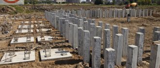
Lighting poles are produced and sold from a warehouse in Maloyaroslavets, st. Mirnaya, building 3 (120 km from Moscow). OGK supports from 4 to 10 m are always in stock. Call.
Galvanized metal multifaceted lighting poles are used for artificial stationary electric lighting of highways, streets, parks and squares, construction sites, public transport stops, industrial and social facilities.
produces non-power faceted conical supports with a flange connection to the foundation block and heights from 3 to 16 meters. OGK supports of our production are manufactured in accordance with GOST 23118 / GOST 32947 from steel sheet with a thickness of 3-4 mm. The support mast has an 8-sided cross-section and has a conical longitudinal shape.
Selection of structural type of reinforced concrete supports
The design feature of supporting devices must take into account the operating conditions of the area. It is also worth understanding that lighting installations must ensure safe movement on the streets. Reinforced concrete lighting fixtures can be used in both urban and suburban environments. The installation of lighting poles is considered suitable for highways, pedestrian streets, and industrial areas. Warehouse complexes, etc. are illuminated using the system.
Reinforced concrete supports are suitable for overhead lines with voltages up to 10 kV. The shape of reinforced concrete structures can be very different. Reinforced concrete lighting poles are of a complex structural type. Brands of devices suggest that the design of the OGK can be:
- octagonal;
- annular;
- round conical;
- faceted conical;
- trapezoidal.
Installation of OGK requires a certain sequence of work.
If the project, agreed upon with local management, includes the installation of reinforced concrete options, changing the characteristics of the equipment is under no circumstances allowed. In addition, the documentation initially provides for installation rules.
The main installation methods involve the use of a reinforced concrete foundation. The devices are attached with flange fastenings or special studs to a metal embedded material located directly in the foundation. Upright type devices are fixed into an earthen pit, into which reinforced concrete mixture is also poured.
Sometimes the sequence of work involves drilling wells. Their depth should be 1.2 m, with a margin of width. The concrete mixture is poured into this free space. This composition is thoroughly compacted using special construction tools. It is planned to prepare a trench for the well and ground the supports. The power cable is laid in it.
Choosing a method for installing reinforced concrete supports
The choice of installation method for lighting poles is purely individual. Projects typically take into account factors such as:
- relief of the territory;
- required degree of illumination;
- energy power;
- number of devices involved;
- method of installation of load-bearing components;
- possibilities of local electrical networks.
Installation of lighting stands made of OGK reinforced concrete implies a mandatory stage of project preparation. Project approval requires compliance with certain rules. The current order includes:
- applying markings in the terrain where work is required;
- subsequent digging of holes, the standard dimensions of which are 1x1 m wide, 1.2 m deep;
- deepening the hole - involves creating a meter-long hole;
- fixing the support post, followed by adding crushed stone, as well as compacting it.
To make the base more reliable, it is customary to strengthen the bottom of the pit with cement mortar. In this case, the lamps should be installed only after the complete completion of work on the arrangement of the pillars. Then the lamps are screwed into the fixtures.
The established standardization rules make it possible to use both reinforced concrete and metal supports. A reinforced concrete structure includes reinforcement that takes on tensile loads. At the same time, concrete has the ability to compress. The equipment also includes input panels. They provide the electrical connection. Many parameters of this type of support meet high quality standards. The strength of main-type pillars is especially high. The cost of reinforced concrete products is lower than the price of metal supports.
In order for the lighting system to be truly effective as a result of the work, the distance between the lighting supports must be correctly determined. This calculation necessarily includes the power value of the lighting devices themselves, their number, as well as the height of the supports. From the support to the curb, certain parameters must also be observed. To achieve certain effects, folding cobras are sometimes used. This information is largely interconnected with the type of illuminated object.
Reinforced concrete supports require periodic condition inspection. For example, metal structural elements should not contain corrosion. The condition of the support itself prevents the appearance of cracks. Bolted connections and anchor bolts mean trouble-free operation for several years. Input electrical panels are maintained by local distribution zone services.
The area adjacent to the building should be well lit. Moreover, the lighting system must be organized in such a way as to cover as large an area as possible. Street lighting poles are used for this purpose.
These structures are usually divided, first of all, according to the material from which they are made. Metal supports have the best characteristics. However, structures made from other materials also have some advantages and are still widely used in lighting.
SV 110-5 buy
Buy SV 110-5
you can contact our managers by phone. You can also consult Norma-cable employees on the characteristics, possibilities of using racks, and also find out the final price for SV 110-5, taking into account discounts and special offers.
Characteristics of reinforced concrete racks (supports) of power transmission lines, grade SV
| Rack brand | Dimensions, mm | Unit weight tn. | Bending moment, tf*m. | Frost resistance | Waterproof | Concrete class | ||||||
| L | b | b1 | h1 | b2 | h2 | |||||||
| SV 95-2 | 9500 | 165 | 150 | 240 | 150 | 165 | 0,75 | 2,0 | F 1 200-300 | W6-8 | B30 | 27 |
| SV 95-3s | 9500 | 165 | 150 | 240 | 150 | 165 | 0,75 | 3,0 | F 1 200-300 | W6-8 | B30 | 27 |
| SV 95-3 | 9500 | 185 | 171 | 265 | 175 | 165 | 0,90 | 3,0 | F 1 200-300 | W6-8 | B30 | 22 |
| SV 110-35 | 11000 | 185 | 170 | 280 | 175 | 165 | 1,13 | 3,5 | F 1 200-300 | W6-8 | B30 | 18 |
| SV 110-5 | 11000 | 185 | 170 | 280 | 175 | 165 | 1,13 | 5,0 | F 1 200-300 | W6-8 | B30 | 18 |
| SV 110-49 | 11000 | 185 | 170 | 280 | 175 | 165 | 1,13 | 5,0 | F 1 200-300 | W6-8 | B30 | 18 |
| SV 164-12 | 16400 | 200 | 210 | 380 | — | 390 | 3,55 | 12,0 | F 1 200-300 | W6-8 | B30 | — |
| SV 164-20 | 16400 | 200 | 210 | 380 | — | 390 | 3,55 | 20,0 | F 1 200-300 | W6-8 | B40 | — |
Legend: L
— stand length;
h 1
;
h 2 - height of the rack at the base and top;
b ;
b 1 ; b 2 - width of the rack at the base and top
Reinforced concrete light supports
help support various lighting fixtures.
When preparing construction work, it is first necessary to secure a construction site. This work includes selecting the type of lighting device and installation method. Several types of building materials are used as support, including reinforced concrete. The latter is the most stable, but has certain disadvantages. Reinforced concrete structures for external lighting
are very dependent on weather conditions and temperature changes, but have a long service life.
Reinforced concrete light poles have several important advantages that distinguish them from all other types of supporting structures:
- protection against rust, decay and chemicals;
- long service life. If you carry out high-quality installation and transportation, the costs will be low;
- high-level fire protection;
- ease of manufacture, convenient repairability;
- no high costs for any work.
In addition, reinforced concrete lighting stands have certain disadvantages, due to which they may not be suitable for the construction of certain types of objects:
- significant supporting weight makes loading, installation and transportation of elements more difficult and, accordingly, more expensive;
- it is impossible to remove a reinforced concrete column without special transport;
- processing and removal of the pole is very complex and costly;
- lighting poles react very poorly to temperature and any weather changes;
- Reinforced concrete lighting poles are vulnerable to chipping and cracking.
Reinforced concrete supports SV
used for external illumination of streets, sidewalks, industrial areas and highways. They can also be used to illuminate parks and areas near residential buildings.
There are several types of light stands made of reinforced concrete:
- end,
- corner,
- intermediate,
- anchor
When developing light stands for industrial use, tension or frame reinforcement is used.
Light reinforced concrete posts
and are marked depending on the structural mass, reinforcement method and dimensions. In addition, they differ in temperature conditions, level of resistance to cold, moisture absorption capabilities, load and electrical voltage drops.
All information on reinforced concrete street lighting poles was kindly provided by Samara Plant of Reinforced Concrete Products LLC. Here you can buy reinforced concrete products at competitive prices.
Reinforced concrete power line supports are made of concrete, which is additionally reinforced with metal, as the name implies. They are labeled SV, which means “vibrated racks”. They are used for laying 0.4-10 kV power lines.
Classification
Supports are usually classified according to a number of characteristics. In particular, according to the method of introducing current-carrying cables, poles are divided into power and non-power. The former are used to organize overhead lines, the latter - underground.
Power structures are used where underground wiring is impossible for some reason. The internal part of the structure includes a power cable. The height of the air networks is determined by the Construction Norms and Rules (SNiP).
For installation, use brackets for lamps. In addition to brackets, an integral part of the supports are plinths that perform protective (protect the cable from damage and exposure to the external environment) and aesthetic functions.
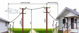
Non-power supports are designed for underground cable laying. The maximum permitted height for this type of pole is 12 m. The cable should be buried in the ground no less than 80 cm. If we are talking about laying under a highway, the laying depth is set to 125 cm.
Note! Non-power poles are not used for installation of high-voltage lines.
According to the installation method, supports are divided into straight-mount and flanged. Installation of the latter begins with placing the embedded element in the ground and its further concreting. When the mortgage is installed, the ground part of the structure is fixed to it using anchor fasteners.
Straight-up supports are a complete structure, the installation of which is carried out in a pre-prepared niche in the ground. The hole is then filled with concrete.
Note! The ratio of the column dug into the ground and the outer parts of the column is determined by the manufacturer. This information is provided on the pole markings.
The following types of supports are distinguished by shape:
- conical faceted;
- conical round;
- tubular cylindrical;
- tubular folding.
Where are lighting poles used?
Lighting lamp posts have a wide range of applications in the industrial sector, public utilities and private households.
Lighting supports are used to arrange the following places:
- Along the highway and tram tracks. Designating this zone makes road traffic safer and reduces the risk of collisions with pedestrians on the edge of the road.
- Sports and children's playgrounds. Single anchor posts or a line with installation of all types of products are used.
- Natural parks. In most cases, centrifuged supports with underground cable laying are used. Wires can only be run through the air in open areas.
- Agricultural facilities (cowsheds, pigsties, poultry houses). Open areas and buildings are illuminated along the perimeter using products of anchor corner and end types. Inexpensive and durable cast racks with overhead wiring are used.
- Industrial objects. Using single lights or lines, lighting is provided for paths and areas, warehouses, parking lots and waste storage areas.
- Regime zones. These include the territories of military units and prisons. All existing types of supports are used.
- In the private sector. Most owners of country houses and private houses opt for centrifuged anchor products.
Purpose
Based on areas of application, supports are divided into the following types:
- High mast. They are used for outdoor lighting of very large areas (for example, stadiums, airports, ski slopes). High-mast structures are offered in a variety of designs, differing in size, type of crowns, number of sections, type of surface (faceted, smooth).
- Street structures for illuminating pedestrian paths.
- Decorative supports. Used to illuminate local areas in gardens, parks, playgrounds, etc. Decorative pillars are always non-power in design. Can be made with faceted or rounded surfaces. Lamps can also vary significantly in their appearance and design, therefore the GOST applied to them will differ. The installation height of decorative systems usually ranges between 2 and 4 m.
- Main supports. The main quality of such poles is their high resistance to mechanical and wind loads.
- Special supports. Used to illuminate individual objects (for example, squares). Designs of this type were used immediately after the advent of electrical networks. They are most often made from pine due to its optimal performance characteristics and low cost.
Types of supports
The supports are made from various materials: metal, wood, concrete, reinforced concrete. In recent years, products made from composites have become widespread.
Metal supports
For the manufacture of supports of this type, steel, cast iron, aluminum and galvanization are used. Galvanized poles are especially popular because they are characterized by high resistance to the negative effects of environmental factors.
Metal supports have the following positive characteristics:
- Light weight and size. The lightest poles weigh about 150 kg, and flanged structures (without mortgages) - about 40 kg. Thanks to their compactness, the transportation of poles is easy: 40 or more sets can be delivered to the site in one trip.
- High strength properties. For production, rolled sheets with a thickness of 3 to 15 mm are used. This is enough to resist serious mechanical loads.
- No difficulties with making changes to the design. To increase or decrease the height of the support, you do not need to abandon the existing structure; it can simply be increased.
- Speed of installation and dismantling work. To install the structure, it is enough to create a hole of the required diameter, place a support in it, and fill it with concrete. For flanged posts, you first need to install the foundation and connect the post to it with a bolted connection.
- Long service life. Outdoor lighting supports are treated with a zinc coating that has anti-corrosion properties. The thickness of such a layer is 80 microns or more, depending on the needs. The service life of the coating is from 50 to 80 years.
- Attractive appearance. Regardless of the purpose, whether we are talking about a decorative pole or a mast one, the supports do not cause rejection by their appearance.
Metal poles also have disadvantages:
- The structure must be periodically painted, otherwise there is a high probability of the material rusting.
- The cost of metal supports is higher compared to competing systems.
Wooden supports
The advantages of wooden poles include the following qualities:
- Light weight. Thanks to this feature, wooden structures are easy to transport and install, which significantly affects the overall cost of the lighting system.
- Easy to install. Often, for the installation of wooden supports there is no need to use specialized equipment.
- Affordable cost of material.
- Moisture resistance. Long service life. However, these qualities are achievable only when the material is impregnated with a special protective composition.
- Insulating qualities to prevent electrical shock.
The disadvantages of wooden structures include the following properties:
- Difficulties with choosing logs of equal dimensions.
- Possibility of destruction of supports due to heavy icing.
- Tendency to rot of material not treated with a protective composition.
Concrete supports
They are among the most common in the post-Soviet space. They were especially often used in the 70-80s.
Among the advantages of concrete pillars, the following qualities should be highlighted:
- low cost;
- long service life (up to half a century);
- ease of maintenance (maintenance of networks is inexpensive).
Concrete structures also have disadvantages:
- instability to moisture (we are talking primarily about groundwater);
- unattractive appearance.
Note! The quality of concrete pillars is determined by the grade of concrete and the method of manufacturing the product.
Reinforced concrete supports
Reinforced concrete pillars are a metal frame structure covered with concrete.
The advantages of reinforced concrete supports include the following characteristics:
- ability to withstand heavy loads;
- durability;
- reasonable cost;
- resistance to temperature changes, which allows the use of poles in areas with cold climates;
- corrosion resistance.
Reinforced concrete products also have disadvantages:
- unattractive appearance repels buyers seeking a decorative effect from the lighting system;
- poor resistance to shock loads.
They produce reinforced concrete products with rounded and faceted surfaces. In recent years, reinforced concrete products have been actively replaced by supports made of more functional materials.
Transportation of reinforced concrete lighting poles
Transportation of poles to the installation site must be carried out using special vehicles equipped with warning signs.
Transportation of products must be carried out in accordance with the following rules:
- To prevent mechanical damage during loading, this process must be carried out using mechanical devices that have a sufficient margin of strength and power.
- The slings must be fastened in two places, located symmetrically relative to the center of gravity of the rack.
- During loading, transportation and unloading, poles should not be subjected to sudden jerks, impacts or being thrown to the ground.
- The use of storage, transportation and loading methods associated with product deflection is not permitted. It is necessary to use special transport, loaders and spacers to ensure uniform distribution of the weight of the racks along their entire length.
- When laying pillars, you need to use wooden supports. At least 4 bars are required for one product. Concrete, plastic and other materials that are hard or excessively soft should not be used as gaskets.
- When installing poles, equipment with a boom must be used, the length of which ensures they are raised to a height sufficient to maneuver over a hole dug in the ground.
To transport reinforced concrete poles, trailers, trailers and trucks with the appropriate body size are used. The best option for combining costs and quality of transportation is a manipulator with a long platform. The vehicle combines the functions of a crane and a truck.
Dimensions of supports
The height, width and weight of products are determined by the material from which they are made. As an example, the following data can be given:
- Wooden poles are produced in five versions: 6.5 m, 7.5 m, 9.5 m and 11 m. The diameter of the poles ranges between 14 and 24 cm. Based on weight, wooden poles are divided into three groups: light, medium and heavy.
- Concrete pillars are heavy. Depending on the size, the product can weigh from 300 kg to a ton. The width of the pillar is from 10 to 40 cm. The height of the structure is within 4-11 m.
- Reinforced concrete supports are offered in the same sizes as concrete ones. However, reinforced concrete products weigh much more because they have a metal component. The weight of a standard design can be between 450-1200 kg.
- For metal products, a minimum height of 1.5 m is accepted (in the case of floor lamps). The thickness, diameter and weight of the lighting system are determined by its tasks and configuration.
The number of sections in a metal lighting mast depends on its height. The three-section mast is 21 meters high. Masts with four sections have a height of 28 m, with five sections - 35 m, with 6 sections - 45 m.
Advantages of reinforced concrete products
The use of concrete products for organizing street lighting is in high demand. This is due to the large number of advantages that the supports are characterized by:
- resistance to corrosion and various negative environmental influences;
- fire resistance and seismic resistance;
- long service life. If the rules of transportation and installation are followed, reinforced concrete supports can last more than half a century;
- low price of structures;
- manufacturability of production.
Installation of reinforced concrete supports for external lighting is carried out according to a pre-designed scheme. Here it is important to take into account the specifics of the soil and the climatic features of the area in order to choose the most durable installation option. The height of the support is also taken into account, since in such cases its weight is much greater. Due to the presence of some difficulties in installation, it is recommended to entrust the work exclusively to competent specialists.
Our online store sells reinforced concrete racks for power line supports and other products of our own production. We offer exclusively proven and reliable products, which allows you to be confident in its quality and compliance with all regulatory requirements. If necessary, our managers will advise you on the available range, announce prices and delivery conditions.
Lighting and power line poles have been used since electricity and lighting became commonplace. And, if at first the poles for installing wiring were made mainly of wood, now more technologically advanced materials are used for the production of these structures.
However, this is not surprising, since metal and reinforced concrete supports, in comparison with structures characteristic of the first half of the last century, are becoming taller, stronger and more resistant to significant loads.
Let's consider what the features of modern lighting poles and power lines are, as well as what and how they are made.
Installation rules
Before installing supports, it is necessary to develop a project taking into account the following circumstances:
- relief of the site;
- desired level of lighting;
- power consumption;
- control and protection system;
- number of light sources;
- method of installation of load-bearing elements and electrical equipment;
- possibility of connecting to the power grid.
During installation work, you must adhere to some rules that directly affect the safety of the system and its service life:
- To carry out electrical installation, all necessary permits from regulatory authorities must be obtained;
- the installation of flanged columns begins only after the concrete has completely hardened (you will have to wait 4-5 days - depending on humidity and air temperature, the type of concrete);
- In order for the flange fastening to be reliable, it is advisable to use castle nuts with a cotter pin;
- It is recommended to treat metal poles with a protective primer and paint material;
- if the installation is carried out in soft soil, you will need to create a cushion consisting of sand and crushed stone mass.
Installation of metal support structures - regardless of their type - differs only in the amount of work and small details. In general, the technological process is very similar.
Preparatory work
Before starting work, prepare a trench for laying the power cable. The recess should have a square cross-section, where the side will be equal to 1 m. The depth of the hole is 80 cm or more (depending on the type of pillar being installed).
The bottom of the pit is covered with a layer of sand mixed with crushed stone. If only sand is used, it is moistened with water. This base is easier to compact.
Laying the power cable
The next step is connecting the power cable to the lighting fixture. This is done underground or above ground. Most often, the cable is laid underground. A layer of clean sand is poured under it. Signal tape is placed on top. Its presence will prevent accidental damage to the line and electrical shock.
Attaching the brackets
There is a special hole at the bottom of the support. The power cable is inserted through it, then pulled upward. When this operation is completed, brackets for the lamps are secured at the top of the support. The number of horns on the bracket is selected in advance - before installation begins. Next, the lamps are connected and light bulbs are installed in them.
Installation of metal supports
A pole is installed in the well, centered, aligned vertically and secured with temporary spacers. The correct installation is checked using a building level. Fill the voids in the well with concrete. When it is completely dry, remove the supports. The support structure for street lighting has been installed.
However, before putting the support into operation, it is necessary to carry out a number of more works, including checking the integrity of the cable. It is also necessary to create a grounding connection. Without it, the system cannot be considered safe to use.
To organize grounding you will need a grounding cable. One end of it is attached to a bolt (located at the bottom of the post), where the power cable is inserted. The second end is fixed to the ground loop.
Note! The ground loop resistance must be at least 40 ohms.
Two types of grounding systems are most in demand today:
- Three-phase networks with tightly grounded neutrals. TN-S provides high quality protection against electric shock. Such systems are installed near schools and crowded streets.
- For street lighting, it is recommended to use insulated conductors with four cores with a cross-section of 25 mm. Inside the cable there is a galvanized steel strip that acts as a grounding device.
The posts are installed in such a way that they are located on not too damp areas of the ground. The distance between the supports is selected so that the lighting fixtures fully illuminate all the necessary areas. At the same time, the lamps should not emit powerful streams of light into the windows of nearby buildings. Avoid overlaps of light fluxes from different lamps.
Firstly, this is a waste of electricity, and secondly, in such areas the lighting will be too bright.
Installation of flange supports
After installing the embedded blocks (flange supports), they are centered. This is done using reinforcement driven into the walls of the trench. Next, concrete is poured into the holes and compacted with a vibrator. The stand is bolted to the mortgages. The installation is completed by attaching the sip cable to the sfg (power faceted flange).
How to determine the spacing between lighting poles
There is an average value of the span between the lamps, which is in the range of 35-45 m. The maximum this parameter can reach is 65 m. When calculating, the requirements for the average horizontal illumination of the road surface must be taken into account. It is measured in lux (lux) and is determined by several parameters:
- congestion of the route - the highest traffic intensity in both directions;
- object category by lighting;
- type of road.
The requirements for the average horizontal illumination of the road are reflected in paragraph 4.1, table 1 of GOST R 54305-2011. For convenience, the data is presented in table form.
Another rule when calculating the distance between lighting poles on a highway or in the city is the dependence of the pitch on the height of the suspension of the lamps. It should not exceed the following ratios:
- 7:1 – with chess placement;
- 5:1 – for axial, rectangular and one-sided arrangement.
The implementation of street lighting is much more complicated than household lighting. This is due to the existence of many rules and requirements. First of all, lighting should be as functional as possible, and the devices involved in it should have a long service life. If all standards are not followed, street lighting will not be effective. For its successful implementation, the most important point is the calculation of the interval between future poles for lamps. The placement of lighting poles in the city center is much simpler than on its outskirts or in the private sector, not to mention villages.
Installation cost
To calculate the cost of pillars, you need to have information about their size and type of structural material. Prices for wooden supports vary between 2-7 thousand rubles. Concrete structures cost from 4 to 13 thousand rubles, reinforced concrete products - from 5 to 15 thousand rubles. Metal supports are estimated to be the most expensive - up to 20 thousand rubles.
The costs don't end there, as the supports still need to be installed. The cost of screeding, drilling wells and installation can be around 3-4 thousand rubles per column. You also need to purchase a street lamp, the cost of which can range from several hundred to thousands of rubles.
Reinforced concrete power line supports are made of concrete, which is additionally reinforced with metal, as the name implies. They are labeled SV, which means “vibrated racks”. They are used for laying 0.4-10 kV power lines.
Stand SV 110-5
Reinforced concrete products are used in the construction of various types of reinforced concrete structures, including in the electrical power industry. The factories produce a wide range of reinforced concrete products: wall and foundation elements, rings, beams, and other products. Reinforced concrete racks are used in the construction of power lines.
Stand brand SV 110-5
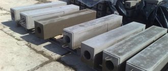
one of the most common in the construction and reconstruction of power lines. Reinforced concrete products have a number of advantages over wooden and metal supports. Support SV 110-5 is a trapezoidal reinforced concrete pillar. It must be manufactured in accordance with GOST 23613-79.
The reinforced concrete rack SV 110-5 was developed for laying power lines with voltages from 0.4 to 10 kV. Also, these supports can be used for the construction of lighting electrical networks.
Characteristics of reinforced concrete transmission line racks
⇒Reinforced concrete pillars are made of different brands and are designated in this way, for example, concrete post SV 95-2, where 95 is the length of the post in decimeters, and 2 is the conditional load-bearing capacity.
According to GOST 23009-78, racks are manufactured in the following standard sizes:
- L – 9.5 meters (NE 95)
- L – 10.5 meters (CB 105)
- L – 11 meters (NE 110)
- L – 16.4 meters (NE 164)
They also differ in the method of reinforcement, on which the load-bearing capacity depends.
Power transmission line support racks SV 95
Reinforced concrete poles SV 95 are widely used for laying and installing networks with a voltage of 0.4 kV and for laying communication lines. They are mainly used for, when installing an additional electric pole. For their manufacture, heavy concrete (class B30) is used, which complies with GOST 26633-91 standards. As a filler for this concrete, manufacturers use granite crushed stone with a strength index of at least M 1200 - M 1400, frost resistance F 300.
SV 95 racks can be operated at temperatures reaching -55 degrees Celsius. They are successfully operated in areas of category IV and can be installed where seismicity does not exceed 7 points on the Richter scale. Reinforced concrete power transmission line supports SV 95.2 and SV 95.3 are equipped with embedded products necessary to fasten structures and connect the necessary grounding elements. These racks taper towards the top and their length is 9.5 meters. The cross-section of the supports is rectangular and equal to: height at the base – 240 mm, at the top – 165 mm, width at the base and top is the same – 150 mm. The weight of the rack is 750 kg.
The SV-95 reinforced concrete pole at the manufacturing enterprise is supplied with embedded iron products intended for connecting structures and grounding parts.
Racks SV 110
Reinforced concrete racks SV 110 are designed for power lines with voltages up to 10 kV. They can also be installed for communication lines. Reinforced concrete poles SV 110 are resistant to aggressive environments, low and high temperatures and can be successfully installed in areas with a high degree of fire danger.
Reinforced concrete pillars SV 110 also find their use as... Their production is carried out using heavy concrete using the vibrocompression method. These concrete mixtures have a compressive strength class of B30.
The length of the SV 110-3.5 and SV 110-5 stands is 11 meters. At the base of the support the height is 280 mm, and at the top the height is 165 mm. The width of the base is 170 mm, the top is 175 mm. The weight of the concrete support is 1150 kg. The SV 110-3.5 posts have a design bending moment of 35 kNm, and the SV 110-5 posts have a design bending moment of 50 kNm.
Reinforced concrete supports SV 110 are made of heavy concrete with the following characteristics:
- Strength grade – M 400
- Frost resistance – F 200
- Waterproof – W 6
Each of them is equipped with embedded metal products designed to secure structures and connect parts of the grounding structure and are manufactured in strict accordance with GOST and TU standards.
All supports must have a certificate of conformity and a quality passport.
Concrete external lighting poles are used in urban and suburban environments. They are designed to illuminate highways, streets, sidewalks, industrial zones, and other objects. This street lighting system is also used as illumination of power lines under voltage of 10 kV. For power lines with voltages above 35 kV, such lighting supports are made from centrifuged concrete.
Reinforced concrete lighting poles are manufactured in various sizes and shapes using vibrocompression and centrifugation technologies. High-quality concrete and reinforced metal wire are used as consumables.
In this article:
Conclusion
So, we have reviewed general information about how the production of reinforced concrete supports is carried out. We also found out what these structures are, what their technical and operational characteristics are.
Are there any questions that require clarification? You can find more useful information by watching the video in this article.
| Rack brand | Dimensions, mm | Unit weight tn. | Bending moment, tf*m. | Frost resistance | Waterproof | Concrete class | ||||||
| L | b | b1 | h1 | b2 | h2 | |||||||
| SV 110-5 | 11000 | 185 | 170 | 280 | 175 | 165 | 1,13 | 5,0 | F 1 200-300 | W6-8 | B30 | 18 |
Advantages of reinforced concrete lighting poles
- Excellent resistance to corrosion, rotting, chemical and mechanical influences.
- They have a fairly long service life. If the requirements for production and installation are met, as well as the correct transportation of structural elements, such illuminators can last more than 50 years.
- Minimum operating costs.
- Reinforced concrete structures are characterized by increased fire resistance.
- The products are not difficult to manufacture and can be easily repaired.
- Maintenance of concrete reinforced lighting structures does not require significant financial expenses.
Disadvantages of reinforced concrete structures for street lighting
- The difficulty of loading/unloading, transporting and installing elements made of reinforced concrete due to the rather large mass. For loading, unloading and installation work, it is necessary to use special equipment.
- It is difficult to dismantle the structure; special equipment is also required.
- Significant costs for disposal or recycling of reinforced concrete supports.
- Concrete products are quite sensitive to changing weather conditions and sudden temperature changes.
- Lighting devices on reinforced concrete supports are prone to cracking and chipping, which cast doubt on the reliability of the product.
Types of concrete reinforced lighting posts
Reinforced concrete pillars are divided into the following types:
- corner;
- intermediate;
- end;
- anchor
For industrial use, concrete racks are reinforced in two ways:
- frame;
- tension
The products differ from each other in reinforcement technology, weight, overall dimensions, and accordingly have different markings.
Different designs of reinforced concrete lighting stands differ in the following operational properties:
- resistance to wind and ice loads;
- level of frost resistance;
- operating temperature;
- concrete density;
- level of moisture absorption;
- electrical voltage drop.
Production technology
The process of manufacturing external lighting devices on reinforced concrete racks is divided into several stages:
- preparation of fittings;
- preparation of concrete solution;
- preparation of forms;
- pouring concrete mixture into molds;
- drying the finished support.
Preparation of fittings
At this stage, a selection of fittings of the required type and size is made. It is cut, for which special equipment is used, and contour spirals are screwed in.
Preparation of concrete mortar
To produce a concrete mixture, a certain brand of cement, mineral and chemical additives are taken. All components are placed in a concrete mixer, water is added in the prescribed proportion, and the mixture is mixed until smooth.
Preparing Molds and Cores
To manufacture directly reinforced concrete racks for lighting equipment, special molds are used, which are thoroughly cleaned and lubricated before pouring the concrete mixture. First, metal spirals are placed into molds, then the rod is made. The steel rod is preheated, then pulled through the spiral and fixed in the container.
Pouring concrete mixture into molds
When the reinforcement is placed in the container, the prepared solution is poured. A special vibrator is used to compact it into the mold. The surface is leveled using an ordinary construction trowel.
Drying the finished support
After completing all the main stages of production, the product is dried. The concrete product in the mold is covered with PVC film (to prevent moisture from entering the structure), and the heating is turned on. After a set period of time, the plastic film is removed.
Installation of racks
Installation work begins with the preparation of a project, previously agreed upon with the authorities.
Installation procedure:
- Markings are applied to the area where reinforced concrete supports for the lights will be installed;
- pits are prepared with the following parameters: depth – 1.2 m, width – 1x1 m;
- a hole 1 m deep is made in the center of the pit;
- the reinforced concrete support is fixed in the pit with crushed stone, which is carefully compacted as it is backfilled.
For your information! In certain situations, the bottom of the pit is additionally filled with concrete mortar. This foundation is more reliable. After installation is completed, lighting equipment is mounted on the racks and lamps are screwed in.
Technology for manufacturing overhead line supports from metal-reinforced concrete
So, after we have determined the technical and operational characteristics of reinforced concrete supports intended for laying overhead lines, we will consider the technology of their manufacture using the example of the SV 95 modification.
Step-by-step production instructions. The first - preparatory stage involves the following work.
Preparation of the working mixture:
- Preparation of Portland cement, inert materials, chemicals. additives and water in accordance with the proportions given in the design documentation;
- Dosing of components and loading into a concrete mixer;
- Bringing the mixture to a homogeneous consistency and unloading it into a concrete paver.
Preparation of reinforcing metal structures:
- Trimming reinforcing bars of the required class into pieces of the required size;
- Preparation of anchor heads;
- Formation of contour spirals;
- Forming loops and preparing the ground loop rod.
Preparation of forms:
- Cleaning the internal volume of the mold;
- Lubricating the internal volume with agents that prevent concrete sticking;
- Spiral distribution;
- Carrying out isothermal heating of rods;
- Distribution of heated rods onto pre-laid stops;
- Threading a spiral between the rods and then attaching it to the rods at three points;
- Distribution of liners along the ends of the mold;
- Installation of pipes and technological loops with their obligatory fixation to the internal surfaces of the formwork.
The second stage is production. At this stage, the working mixture is poured and the finished product is formed.
The following work is performed in the process:
- The concrete paver conveyor is installed in the working position and the pre-prepared form is filled with mortar. Filling the form with concrete is carried out by moving the paver along.
- The mixture is compacted using a deep vibrator to prevent the formation of voids.
- Workers with their own hands, using a rule or a trowel, level the surface of the laid material in the mold.
At the third stage, the product is subjected to isothermal treatment.
This is done as follows:
- Thermal insulating material is laid on top of the filled formwork.
- The heating system for the internal volume of the formwork is turned on. The system automatically controls the parameters of temperature, time, etc. Therefore, the influence of the human factor on the quality of the product is minimal.
- The covering material is removed.
At the final stage, the mold is dismantled, the reinforcement is cut, quality is checked and the finished product is shipped to the warehouse.
Grounding of reinforced concrete racks
Grounding devices are installed on reinforced concrete racks intended for power lines with voltages up to 1 kV. They are necessary to discharge lightning surges into the ground. The lighting equipment itself is similarly grounded. The housings of lighting devices are connected to the ground loop.
The grounding loop is made of steel pins (diameter from 6 mm) and corners. They are installed in a triangle and connected to each other by a strip of metal. The grounding device must have a resistance of up to 30 ohms.
SV 110-5 characteristics
- geometric volume - 0.5698 cubic meters;
- design bending moment - 5 tf*m (tf - ton-force or 9806.65 N in SI units);
- support weight - 1125 kilograms;
- the volume of concrete per rack is 0.45 cubic meters.
Power lines using SV 110-5 are allowed to be built in various climatic conditions, including that they can withstand seismic activity of up to nine points on the Richter scale, as well as temperatures of up to minus 55 degrees Celsius.
