Shotcrete - this is the application of one or several layers of cement-sand mortar (shotcrete) to the surface of formwork, concrete or reinforced concrete under compressed air pressure.
It is used for waterproofing, a protective layer of prestressed wound reinforcement, strengthening thin-walled structures, embedding seams, for repair work and correcting defects in concrete and reinforced concrete.
Shotcrete equipment set:
1 – compressor, 2 – air hoses, 3 – air filter, 4 – cement gun, 5 – hose for supplying dry mixture, 6 – nozzle, 7 – shotcrete surface, 8 – water hose. 9 – tank
Shotcrete equipment includes a cement gun, a compressor, water and air hoses, air and water filters, nozzles, and a water tank.
Compressed air under a pressure of 0.2...0.25 MPa is supplied from compressor 1 through air hoses 2 to air filter 3, where it is cleaned of dust, oil and other impurities.
Purified air is supplied to cement gun 4, which is pre-loaded with a dry mixture of sand and cement.
The dry mixture is then directed through hose 5 to nozzle 6 and at the same time water from tank 9 under a pressure of 0.35...0.5 MPa is also supplied to the nozzle to moisten the mixture.
The moistened mixture flies out of the nozzle in the form of a fan-shaped torch at a speed of 100 m/s.
Sand particles covered with a cement film collide with the formwork or reinforced concrete structure and stick to it.
Due to the high speeds of movement of the mixture, the existing excess of chemically unbound water is removed from the particles in flight.
Thus, a layer of sand concrete gradually builds up on the surface, and sand particles penetrate into the previously applied layer and compact it.
The result is a dense concrete structure that has low water permeability and high strength.
In one cycle, a shotcrete layer with a thickness of 25...30 mm is applied.
With multilayer shotcrete, the time between the application of each layer is determined experimentally.
The previously applied shotcrete must have sufficient strength and, at the same time, ductility to withstand dynamic loads when applying the next layer.
For shotcrete, clean sand with a moisture content of no more than 6% and a particle size modulus of 2.5...3 is used.
Inclusions of grains larger than 8 mm are not allowed.
Cement of grade 500 and higher is used as a binder, and quick-hardening cements are used to create waterproof shells and repair reinforced concrete structures.
To obtain a dense layer of shotcrete of uniform thickness, during application the nozzle is kept at a distance of 0.7... 1 m from the surface being shotcrete (moved in a circular motion), and the mixture jet is directed perpendicular to it.
On vertical, inclined and curved surfaces, a shotcrete layer is applied from bottom to top so that the freshly applied shotcrete does not slide off them.
The viscosity of the mixture is adjusted by dosing the water supply.
The thickness of the applied layer is controlled by beacons.
Ceilings and vertical surfaces are shotcrete in several layers, and floors are shotcrete for the entire thickness at once.
Before shotcreting, the surface is cleaned with compressed air and moistened.
The first time a layer of shotcrete is applied from below to a height of 1.3..1.5 m.
When applying subsequent layers, their overlap areas must be at least 20 cm.
The overlying layers are applied from mobile or stationary scaffolds.
After applying the first layer, the concrete is kept and moistened.
In hot weather, the surface of the shotcrete layer is covered with a tarpaulin or film covering, which prevents rapid evaporation of moisture.
When the concrete gains the required strength, a second layer is applied, etc.
Pneumatic concrete is the application of plastic concrete mixtures using fine-grained aggregate to the surface.
Mixtures, as a rule, are prepared centrally at a concrete plant or at a construction site in a mixer of the Pneumoconcrete installation.
In this way, structures up to 150 mm thick are concreted: thin-walled coverings of domes, shells, structures for storing liquids (tanks), swimming pools, cooling towers, joints of prefabricated reinforced concrete structures are sealed, and concrete and reinforced concrete structures are repaired (restored).
Concrete laid in this way is distinguished by high physical and mechanical properties (density, water resistance, frost resistance and adhesion to various surfaces).
Installation diagram “Pneumatic concrete”:
1 – skip hoist, 2 – receiving and mixing device, 3 – vibrating sieve, 4 – mortar pump, 5 – hose, 6 – nozzle, 7 – concreting surface
Concrete mixtures are applied using an installation that includes a receiving and mixing device 2 with a forced mixer, a feeder, a vibrating sieve 3 with 10×10 mm cells, hoses 5, an air pipeline, a nozzle with a mixture speed damper 6.
As a receiving and mixing device 2, a mortar mixer SB-97 or a forced action SB-80, equipped with a skip hoist 1, is used. The mixture is transported using mortar pumps S-683, S-684 or S-317B with a supply of 2.4...6 m3/h, converted on a direct-flow circuit and equipped with an additional mixing chamber.
Hose 5 is mounted from separate sections with an internal diameter of 50 or 63 mm.
A nozzle is attached to the end of the hose.
When leaving the nozzle, the speed of the mixture is 70...90 m/s.
The configuration and geometric dimensions of the nozzle depend on the type of work, the materials used and the position of the nozzle in relation to the concrete surface.
The consumption of compressed air with a pressure of 0.7 MPa is 7...9 m3/min.
Before starting work, connect the installation to the electrical network and water supply, install scaffolding or mobile scaffolding so that the distance between the flooring and the working surface is 1.2...1.5 m, and the height of the tier is 2 m.
For vertical structures, lightweight formwork is installed.
Slots wider than 5 mm in the formwork are not allowed.
When applying the mixture, the nozzle is held perpendicular to the concrete surface and at a distance of 0.7...1.2 m from it.
Concrete mixture is applied to vertical surfaces from bottom to top.
To obtain a uniform thickness of the concrete surface, the nozzle makes spiral-shaped translational movements.
To create normal hardening conditions, concrete is protected from exposure to wind and direct sunlight, impacts, shocks and other mechanical influences, and it is periodically moistened.
Description of the concept
The surface modulus is the ratio of the cooled or heated area using a building material to its volume. This parameter is important both for construction and for the operation process, since it determines the conditions of use and durability of the material.
You may be interested in: Insulation thickness for walls: formulas, calculation features and requirements
Mn = S/V – formula:
- MP – surface modulus;
- S – structure area;
- V is the volume of the monolith.
There are several ways to calculate its values, which are intended for real structures. Also, when drawing up the formula, the method of pouring and the presence of additional elements, the thickness of the layer, and the conditions under which the base is dried are taken into account. If the concrete surface is incorrectly calculated, this can lead to the wrong choice of heating technology, the appearance of surface defects, cracks and faults.
You will be interested in: Axor fittings: customer reviews, product quality, manufacturer, installation and use features
When laying the mixture in winter, the main task facing builders is to provide the concrete with the opportunity to quickly harden under conditions under which it would gain all its characteristics. With frequent precipitation, low temperatures, and climatic changes, it is not recommended to lay concrete.
Definition of quality
If we talk about the ideal time for carrying out concrete work outdoors, then this is certainly the warm season. During such a period, as a rule, positive temperatures prevail, there is no large amount of precipitation, stable sun, due to the heating of which the texture of the material quickly hardens. Unfortunately, it is not always possible to work under such conditions; most often construction is carried out at low temperatures.
You might be interested in: How much lining in a cube: units of measurement, number of boards, formula, calculation rules and examples
During the process of concreting under frost, the main problem appears, the essence of which is the increase in the strength of concrete and the beginning of crystallization of water in it. The main methods for solving it include creating thermal insulation of the formwork or special heating of the laid mixture.
The choice of solution depends on how quickly the mold with the embedded material will harden. This can be determined using special formulas and the ratio of the area to the cooled surface and its volume. The concrete surface modulus helps to solve a number of issues and determine how quickly, in contact with cold air, a given area can harden.
When calculating the modulus in winter, one must take into account the fact that the process of concrete gaining strength stops when the temperature cools to 0 degrees. Only those parts of the surface that are in contact with colder air are considered to be cooled.
Experts advise using additional heating elements that will help quickly solve the problem of hardening of the laid monolith.
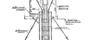
Massive structures and foundations. Monolithic foundations and massive structures or blocks are most often concreted in collapsible formwork from ready-made standardized elements or in spatial block forms. When concreting large masses, large formwork panels with an area of up to 30 m2 are used, installed by cranes.Foundations designed for static loads can be concreted intermittently, but with the obligatory treatment of working joints.
Massive foundations that bear dynamic loads, as well as massive hydraulic structures, are concreted in separate blocks, the dimensions and location of which are provided for in the project. Each block is concreted without interruption.
Embedded parts (for example, anchor bolts, groove structures) are installed immediately before concreting using carefully calibrated jigs, which are secured to special frames that remain in the concrete. During laying of the concrete mixture, the design of the conductors must exclude the possibility of deviation of the embedded parts from the design position. The threads of the bolts installed in the jigs along with the nuts are lubricated with oil and wrapped with roofing felt.
If the embedded parts are not installed before concreting, then grooves are made in the concrete, i.e., sections of the structure intended for the embedded parts are left unconcreted. The fines are concreted after installing the embedded parts in them. The structures are concreted in horizontal layers 0.3...0.4 m thick. The concrete mixture in large masses is compacted with heavy suspended deep-seated vibrators IV-90, collected in packages. The thickness of the compacted layer of concrete mixture reaches 1 m. Flat or volumetric vibrating packages, consisting of four vibrators, are rearranged using lifting cranes.
In hydraulic engineering, when concreting large unreinforced blocks, machines equipped with a package of vibrators are used. Figure 117 shows concreting of a hydraulic structure block using a small-sized electric tractor equipped with a vibrating package and an electric tractor equipped with a blade. The concrete mixture is transported to the placement site by a concrete truck.
For thick reinforcement, manual deep-well vibrators with a flexible shaft are used.
The upper surface of the foundations is compacted with surface vibrators, and then smoothed with a rule in level with the upper edges of the guides or special lighthouse boards (118), as well as with SO-SW machines for grouting the surface (119).
Underlayment layer for floors and floor coverings. A concrete base layer (preparation) is installed under concrete, asphalt and other floors. Rigid concrete mixtures are used for the underlying layer.
In dense soils, the concrete mixture is placed in the underlying layer directly on the graded soil; in weaker soils, on a layer of crushed stone compacted into the soil. In weak soils, the underlying concrete layer is sometimes reinforced with a mesh of reinforcing steel.
Before concreting the underlying layer, lighthouse guide boards are installed, which are nailed to the stakes, behind
beaten into the ground. Lighthouse boards are placed at a distance of 3...4 m from one another, and the upper edge of the board should be at the level of the surface of the underlying layer.
The concrete mixture is laid in the underlying layer and floor covering in strips 3...4 m wide, separated by lighthouse boards. The strips are concreted one at a time. Intermediate strips are concreted after the concrete in adjacent strips has hardened. Before concreting the intermediate strips, the lighthouse boards are removed.
Walls and partitions. Walls and partitions in collapsible formwork are concreted without interruption in sections no more than 3 m high.
Thin walls and partitions less than 15 cm thick, where it is impossible to use trunks, are concreted in tiers up to 2 m high. On one side, the formwork is erected to the entire height at once. Reinforcement is attached to this formwork. The second side of the formwork is first erected to the height of one tier, and after concreting the tier is completed, the formwork of the second tier is installed, etc. The concrete mixture is compacted using deep or external vibrators. Concreting is resumed on the next highest section of the wall or partition only after the construction of the working seam.
If it is necessary to concrete sections of walls and partitions with a height of more than 3 m without working joints, it is necessary to arrange breaks in work to allow the concrete mixture to settle. The duration of breaks should be at least 40 minutes and no more than 2 hours.
When concreting the walls of liquid storage tanks, it is necessary to continuously lay the concrete mixture to the entire height in layers no more than 0.8 times the length of the working part of the vibrator. In exceptional (emergency) cases, it is allowed to construct a working seam followed by careful treatment of its surface.
The joints between the walls and the bottom of the tanks are made in the places provided for by the design.
In large tanks, the circumference is divided into sections with vertical seams and concreted in sections, but it is better to concrete such tanks continuously along the entire circumference.
To make the surfaces of the bottoms and walls of tanks more waterproof, iron plating is used.
The walls in vertical sliding (movable) formwork begin to be concreted, filling the form with concrete mixture to half its height, in two or three layers, compacted with vibrators. Laying two (three) layers of concrete mixture along the entire perimeter should take no more than 3.5 hours. Then the formwork is torn off and raised (continuously) at a speed of 30...60 cm/h until the formwork is filled with concrete mixture to its entire height.
Subsequently, the concrete mixture is placed into the mold continuously in layers of 200...250 mm, not reaching the top by 50 mm. The layers of the laid concrete mixture are no more than 200 mm in height in thin walls (up to 200 mm thick) and no more than 250 mm in other structures. The next highest layer begins to be laid only after the previous one has been laid to a given height along the entire perimeter of the formwork.
Columns. Columns with cross-sectional sides from 0.4 to 0.8 m in the absence of intersecting clamps are concreted without interruption in sections no more than 5 m high, freely dumping the concrete mixture directly from the container into the formwork. When lowering the concrete mixture from a higher height, link trunks are used.
Columns with cross-section sides less than 0.4 m, columns of any cross-section with intersecting clamps that cause stratification of the concrete mixture when it falls, are concreted without interruption in sections no more than 2 m high. In this case, the concrete mixture is supplied through windows installed in the side walls of the formwork . The concrete mixture is compacted using deep or external vibrators. The next highest sections are concreted only after the construction of the working seam.
For higher heights of sections of columns that are concreted without working joints, it is necessary to arrange breaks in concreting to allow the concrete mixture to settle. The duration of the break should be at least 40 minutes and no more than 2 hours.
To strictly adhere to the thickness of the protective layer in columns, special gaskets are used, made from cement mortar and attached to the reinforcement bars before concreting with a binding wire embedded in the gaskets during their manufacture.
The formwork of high columns is installed only on three sides, and on the fourth it is expanded during the concreting process. If over
Beams and purlins with dense reinforcement are located in columns, which does not allow concreting the columns from above, then they can be concreted before installing the reinforcement of the beams adjacent to them.
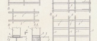
The columns are concreted to the entire height of the floor without working seams. Working seams can only be made at the level of the top of the foundation A-A (120, a) or at the bottom of the purlins and beams B-B.
In the columns of industrial workshops, working seams can be arranged at the level of the top of the foundation A-A (120.6), at the level of the top of the crane beams B-B or at the level of the bottom of the consoles (protrusions) B-C supporting the crane beams. In columns of beamless floors, seams can be installed at the level of the top of the foundation A-A (120, c) and the bottom of the capitals B-B. The capital should be concreted simultaneously with the floor slab.
Frame structures are erected with a break between concreting columns (racks) and frame crossbars, arranging working seams at the bottom or top of the bevel (vut) G - G (120, g).
Ceilings and individual beams. Floors (beams and slabs) monolithically connected to columns and walls are concreted no earlier than 1...2 hours after concreting the columns and walls due to the need for initial settlement of the concrete mixture placed in them.
To form a protective layer in beams and purlins, special gaskets made of cement mortar are used, on which reinforcement is installed. Concrete workers, while concreting, lightly shake the reinforcement using metal hooks, making sure that a protective layer of concrete of the required thickness is formed under the reinforcement.
The concrete mixture is placed in beams and purlins in horizontal layers 30...50 cm thick, depending on the type of vibrator used. If the beams are heavily reinforced, then IV-66 deep vibrators are used for concreting. In large purlins and beams, the concrete mixture is compacted using IV-67 or IV-79 vibrators. At the intersections of the reinforcement of purlins and beams, the concrete mixture is compacted by bayoneting, if it is impossible to use vibrators.
Calculation parameters
If we talk about the practical side, then the calculation of beams, cylinders, and additional transitions in diameter can be quite complex. Therefore, craftsmen simplify it and use several formulas for the main structural elements.
When deducting, such tricks as the length of the beam or the height of the column are used; other indicators do not affect the surface modulus and are not taken into account in the calculations. When calculating, the entire surface is taken into account. True, this calculation will be relevant only if it cools as quickly as possible.
That is, the concrete surface stands on frozen ground or is constantly in contact with cold air. Otherwise, its elements are not taken into account. Builders advise using the concrete surface module when drawing up a building design.
You may be interested in: Number of storeys in a building: definition, types, classification, characteristics, ensuring safety and compliance with legal standards during construction
This will help calculate the necessary data and take measures that will make the hardening process quick and of high quality.
Modulus definition and formula
The modulus for a concrete surface is calculated using the formula: Mп=S1:V. Therefore, the first step is to determine the volume by multiplying the length, height and width. Provided that these indicators of the concreting solution in the cold and warm seasons are equal to 2/3/1, respectively, then the volume is 6 m3. The area is calculated as follows:
- S=4+6+12=22 m2, - for frozen soil;
- S2=4+6+6=16 m2, - in warm soil.
For frozen and warm surfaces, the area differs, since wet soil draws the temperature out of the solution.
The areas differ in the final figures due to the inclusion of edges in the calculation. It is generally accepted that frozen or wet soil draws some heat from the solution, so for a cooled surface the area of one face is added to the formula 2 times. Therefore:
- Mп1=S/V=3.67, - for cooled soil;
- Mп2=S2/V=2.67, - on a warm surface.
The difference in modulus between warm and cold soil is 1 parameter for the same volume of solution. The calculation is carried out to find out the rate of increase in temperature per hour and, accordingly, to perform all methods for warming it up. Depending on the indicator, the method of maintaining heat is selected. For concrete surface modulus values of no more than 6, the “thermos method” is used. The base of the formwork is thermally insulated, plus the solution spontaneously heats up due to the chemical reaction of Portland cement with the liquid.
Methods used to heat concrete: thermos, heating using transformers, adding additives with the effect of accelerating the hardening of the mixture, increasing the temperature of the solution with diesel heaters.
Heating and cooling
Unfortunately, it is unrealistic to ensure high-quality simultaneous heating or cooling of concrete along the entire perimeter of the monolith. Any change in conditions, positive or negative, can lead to the appearance of delta temperatures between the core and the surface.
If the delta is small, then there will be no specific effect on the surface, the concrete will gradually harden, and then its basic qualities will appear. But if the temperature is very sharp, then cracks or chips may form on the surface. As for the calculation in practice, the more massive the structure, and vice versa, the larger it will be. If the increase in temperature difference is sharp, this will lead to an increase in internal stresses in the material.
In order to avoid this, builders advise laying with balls, pouring concrete gradually. The temperature in all its parts should be approximately the same. This indicator is also taken into account when drawing up the formula for the concrete surface modulus.
With a surface module of up to 4 meters, the temperature change should not be more than 5 degrees per hour. If it lies in the range from 5 to 10 meters, then the rate of change should not exceed 10 degrees per hour. If the module is more than 10 meters, then the rate of change is no more than 15 degrees per hour.
As for ensuring temperature stability, this factor is possible when using thermal insulation of a concrete monolith. With high-quality heating, the power of the cable for concrete or the use of a heat gun must be constantly adjusted. Without this, chips will form in the event of overheating and rapid crystallization of water on the surface of the concrete.
Concrete surface modulus: definition, calculation examples. Heating and cooling speed
What is this parameter - surface modulus? We have to get acquainted with a new concept and study ways to calculate its values for real structures. In addition, we will touch on the basics of winter concreting and the influence of the surface modulus on the work methods used.
The topic of the article is directly related to winter concreting.
What is it Definition
The ideal time for outdoor concrete work is the warm season. Alas, it is not always possible to wait until spring: in some cases, monolithic construction is carried out even at sub-zero temperatures.
In addition: in a number of regions of the country the warm season is simply too short. In Yakutsk, for example, the average monthly temperature is above zero only five months a year.
When concreting in cold weather, the main problem is to allow the concrete to gain strength before the water in it begins to crystallize. The main methods for solving it come down to thermal insulation of the formwork or heating of the laid mixture. In this case, the choice of a specific solution is determined primarily by how quickly the mold with concrete will cool.
The rate at which a particular structure will lose heat is determined by the ratio of its cooled surface area to volume.
Practical conclusion: an ideal ball will cool the slowest.
The surface modulus of a concrete structure is, in fact, the ratio of its cooled area to its internal volume. The formula for the concrete surface modulus is extremely simple: Mn = S/V, where Mn is the surface modulus; S is the surface area of the structure in contact with cold air, soil or other structural elements cooled below zero; V is the total volume of the monolith.
Since the numerator of the formula is in square meters (m2), and the denominator is in cubic meters (m3), the desired parameter will be measured in strange units described as 1/m, or m^-1.
An important point: since the process of concrete gaining strength practically stops when cooled to 0 degrees (water crystallization temperature), only those parts of the monolith surface that are in contact with colder air, the base or structural elements are considered cooled.
When laying concrete on unfrozen soil, the lower surface of the foundation is excluded from the calculations.
Calculation examples
Let's calculate the parameter we are interested in for a slab foundation measuring 6x10 m and 0.25 m thick, laid at a negative ambient temperature on thawed soil.
- Obviously, all surfaces of the slab will be cooled, except the bottom : it is in contact with the ground, which has a temperature above zero. We add up their areas: (6 x 0.25) x 2 + (10 x 0.25) x 2 + 6 x 10 = 3 + 5 + 60 = 68 m2.
- We calculate the volume of the slab . It is equal, as we remember from the school geometry course, to the product of the sides of a rectangular parallelepiped: 10 x 6 x 0.25 = 15 m3.
- We calculate the surface modulus : 68 m2 / 15 m3 = 4.5(3) 1/m.
- The mixture is heated before placing in the mold. In this case, with proper thermal insulation, the cooling period to a critical temperature (0 degrees) increases; Moreover, hot concrete sets and gains strength much faster.
In practice, calculations of beams, cylinders with diameter transitions and other structures can be quite complex and take considerable time. Like all people, builders tend to simplify their lives whenever possible; For this purpose, there are several simplified calculation formulas for the main structural elements.
| Structural element | Calculation formula |
| Beams and columns of rectangular cross-section with section sides equal to A and B | MP = 2/A + 2/B. The length of the beam or the height of the column does not affect the surface modulus and is not taken into account in the calculations. |
| Beams and columns of square cross-section with side section equal to A | MP = 4/A |
| Cube with side A | MP = 6/A. In this case, all surfaces of the cube are taken into account; the calculation is relevant for the case when they are all cooled (the cube stands on frozen ground and is in contact with cold air). |
| A free-standing parallelepiped on frozen ground with sides A, B and C | MP = 2/A + 2/B + 2/C |
| A parallelepiped with sides A, B and C, one of its faces adjacent to the warm mass | MP = 2/A + 2/B + 1/C |
| Cylinder with radius R and height C | MP = 2/R + 2/C |
| Slab or wall thickness A, cooled on both sides | MP = 2/A |
An illustrative example: a monolithic wall is cooled on both sides.
What to do about it
So, we have learned to calculate a certain parameter that affects the cooling rate of the array in the cold. And how to apply it in real construction?
Heating and cooling speed
Since it is impossible to ensure simultaneous heating or cooling of concrete throughout the entire volume of the mass, any change in conditions willy-nilly will lead to the appearance of a temperature delta between the core and the surface.
Attention: this delta will be larger, the more massive the structure. That is, simply put, the smaller the ratio of its area to volume.
An increase in the temperature difference between the core and the surface will inevitably lead to an increase in internal stresses in the material; Since we are talking about concrete that has not gained strength, cracks are not only possible, they are guaranteed.
Consequences of rapid cooling.
Exit? It comes down to slowing down the change in the surface temperature of the array as much as possible.
| Surface modulus | Rate of temperature change |
| MP up to 4 1/m | No more than 5 degrees/hour |
| MP lies in the range of 5 - 10 1/m | No more than 10 degrees/hour |
| MP more than 10 1/m | No more than 15 degrees/hour |
Temperature stability during cooling is ensured, as a rule, by the thermal insulation of the concrete monolith; when heating - by adjusting the power of the cable for concrete or a heat gun.
Choosing a temperature maintenance method
This use of the obtained surface modulus value is directly related to the calculation of the heating/cooling rate: based on the calculation performed, a method is selected to stabilize the temperature before the concrete gains strength.
For a surface modulus of no higher than 6, the so-called thermos method is sufficient. The form is simply qualitatively thermally insulated, which significantly reduces heat transfer.
In addition: during the process of hydration (chemical reactions of Portland cement with water), a fairly significant amount of heat is released, which contributes to the self-heating of the mixture.
For MP in the range 6 - 10 1/m, several solutions are possible:
Pouring with hot concrete.
- Additives are added to the mixture to accelerate its hardening. As an option, high-grade fast-hardening Portland cements are used, which, in addition to accelerating strength development, are useful because they emit more heat during the hydration process.
- An alternative approach is to lower the crystallization temperature of water in the hardening concrete mixture. Thanks to appropriate additives, strength development continues at subzero temperatures.
Useful: it is worth cautioning against using saline solutions for this purpose. Their price is really lower than specialized synthetic additives; however, it is neutralized by the high (from 5%) salt content in the mixing water. At the same time, a high salt content reduces the final strength of concrete and contributes to accelerated corrosion of reinforcement.
Finally, for surface modulus over 10, the only sensible solution is to heat the concrete with a heating cable or heat guns until a certain percentage of the design strength is reached. The value of the minimum strength before freezing depends on the class of concrete and the area of use of the monolith; Complete instructions for selecting values are contained in SNiP 3.03.01-87.
The structure is heated until it reaches full or partial strength.
| Construction, concrete class | Minimum Strength |
| Monoliths intended for use inside buildings; foundations for industrial equipment that are not subject to shock loads; underground structures | 5 MPa |
| Monolithic structures made of concrete B7.5 - B10, used outdoors | 50% vintage |
| Monolithic structures made of concrete B12.5 - B25, used outdoors | 40% vintage |
| Monolithic structures made of concrete B30 and higher, used outdoors | 30% vintage |
| Prestressed structures (made on the basis of a stretched reinforcing frame made of elastic steels) | 80% vintage |
| Structures loaded immediately after warming up with the full design load | 100% vintage |
Stripping
After achieving the minimum required strength and stabilizing the temperature of the monolith, the formwork is removed and the thermal insulation is removed. Since this occurs at subzero temperatures, the delta between the concrete surface and the surrounding air is also important and is also tied to the surface modulus.
From the moment the formwork is removed, rapid cooling of the monolith begins.
- With MP in the range of 2-5 and a reinforcement coefficient (the ratio of the total cross-section of the reinforcement to the cross-section of the monolith) of up to 1%, the maximum permissible temperature delta is 20 C.
- With a reinforcement coefficient of 1 to 3 percent, the maximum temperature delta is 30 degrees.
- With a reinforcement ratio above 3%, the air can be 40 degrees colder than the concrete.
- When the surface modulus is over 5 1/m, the maximum permissible temperature differences for different reinforcement coefficients take values of 30, 40 and 50 degrees, respectively.
Treatment of winter concrete
If, after gaining full strength, winter concrete and monoliths made from unprepared concrete of normal humidity are processed quite traditionally, then perforation and arrangement of openings in the monolith before it gains strength has its own specifics.
Simply put, frozen concrete that has not reached its original strength should not be crushed with a jackhammer or hammer drill. In this case, cracks may appear.
Before reaching full strength, concrete cracks easily.
The optimal way to construct openings is to create formwork for them at the stage of pouring the monolith. Among other things, in this case it is possible to fully anchor the edges of the reinforcement along the edges of the opening. Where this is impossible and the opening will have to be cut in place, corrugated reinforcement is used: the corrugation on its surface itself serves as an anchor for the rod.
Useful: to make a hole (for example, a vent or to enter communications in a strip foundation), when pouring it with your own hands, it is enough to lay an asbestos-cement or plastic pipe of the appropriate diameter into the formwork.
The photo shows the simplest way to install vents.
For the actual processing where it is impossible to do without it, a diamond tool is preferable. Diamond drilling of holes in concrete does not require the use of impact mode; as a result, there is less likelihood of cracks and chips. Cutting reinforced concrete with diamond wheels leaves the cut edges perfectly smooth and, which is very convenient, does not require changing the cutting wheel when cutting reinforcement.
Related concept
A simple associative chain will force us to touch on another concept related to concrete structures. This is the so-called Young's modulus for concrete (also known as elastic modulus or deformation modulus).
A visual representation of the meaning of the term.
The modulus value is determined experimentally, based on the results of testing a sample, measured in pascals (more often, taking into account high values, in megapascals) and denoted by the symbol E. To be honest, this parameter is of interest only to specialists and is not taken into account in low-rise construction.
Simply put, this parameter describes the ability of a material to deform briefly under significant loads without irreversible damage to the internal structure. Even easier? Please: the higher the modulus of elasticity, the less likely it is that a piece of concrete will break off from the foundation when hit with a sledgehammer.
After this definition, it is logical to assume that the modulus of elasticity (or deformation) is related to the compressive strength and, accordingly, the brand (class) of the material.
Indeed, the dependence is almost linear.
- For heavy naturally hardening concrete of class B10, the deformation modulus is 18 MPa.
- Class B15 corresponds to a value of 23 MPa.
- B20 - 27 MPa.
- The deformation modulus of concrete B25 is 30 MPa.
- Class B40 - 36 MPa.
Complete table of values for different types of concrete.
Conclusion
We hope that we have not bored the reader with an abundance of boring definitions and dry numbers. As always, additional topical information can be found in the attached video in this article. Good luck!
Temperature support
Let's look at the concrete surface modulus in more detail. Almost everywhere there is information about the importance of maintaining a stable temperature. Various techniques can be used for this.
If the surface modulus is in the range from 6 to 10 meters, then it is advisable to heat the mixture before placing it in the mold. With this option, the cooling period to the critical temperature increases, hot concrete sets faster and gains the required strength. This is an effective option for quick work. The second method is to use additional elements that are introduced into the mixture immediately before laying and accelerate its hardening. For example, high-grade fast-hardening Portland cement. This can also be achieved by increasing the amount of concrete.
As for the alternative approach, it comes down to lowering the temperature using water crystallization. Special elements are also added here that increase strength even at low temperatures. With the right choice of hardening method, based on deductions from the surface modulus, you can get a high-quality result and a durable surface without imperfections and cracks.
Routing
This is the main document, which contains information about laying concrete, its technical characteristics, and a list of people taking part in the laying. It also indicates the temperature regime at which hardening will be maximum. The technological map is considered an important document for engineering and technical workers, construction and design organizations.
It can also be used by work producers, foremen and foreman in the process of laying materials. It is mandatory to indicate the authorship of the technological map.
It consists of several categories. The main ones include: scope, organization and technology for performing work, indicating quality requirements, the need for material and technical resources, as well as a listing of the necessary elements that will be used when laying the material.
A mandatory element of the technological map is the presence of a safety solution, as well as technical and economic indicators. Although this document is compiled for a specific area, examples of determining the surface modulus, using a technological map and determining the strength of concrete are also considered mandatory here.
The technological map is a document by which the level of practicality and quality of concrete will be determined. Its obligatory element is the calculation of the concrete surface modulus.
Availability of stripping
After the poured concrete begins to gain the minimum required strength, the temperature on the surface and near the core stabilizes, the formwork is removed and the created thermal insulation is removed. This must occur at sub-zero temperatures. If the temperature regime is not maintained during the process, this leads to a split in the surface.
If the reinforcement ratio exceeds 3%, the air may be several degrees cooler than the concrete. If the surface module is more than 5 meters, the maximum permissible temperature differences take the value of 30, 40 or 50 degrees. This must be taken into account. If we talk about the modulus of the surface of a concrete structure, then its concept is close to the modulus of concrete. But this includes the values of additional elements that are used in the masonry process.
The factor depends on the presence of additives in the main mixture.
Prompt supply and reception of concrete mixture on the structure
Laying concrete mixture from a bucket
After sampling, the concrete mixture is fed into a container from which a vertical structure will be poured, usually buckets, which are then slung onto the hooks of a crane and delivered to the structure to be concreted. At construction sites where the volume of poured structures is insignificant, this process can be organized using buckets, wheelbarrows, winches and other mechanisms.
After the tub is brought to the structure to be poured, the concrete worker begins to lay the concrete mixture in layers into the formwork system. The height of the layer should not exceed the height of the vibrator mace. After the first layer is laid, the concrete mixture is thoroughly vibrated, then the next layer is laid, and so on until the height of the concrete reaches the design mark.
Markings can be given in the form of marks on the formwork using surveying instruments, or, as a less reliable method, simply measured using a tape measure from the edge of the formwork structures. By the way, careful adherence to the height of poured structures during concrete acceptance can subsequently save a significant amount of unnecessary work, in the form of dismantling excess concrete if the structure is poured above the mark and shooting additional plywood or boards in case the structure is underfilled.
Processing concrete in winter
If we talk about processing concrete after it has gained the required strength, then there is nothing special here. But as for the construction of an opening in a monolith before it gains strength, a number of specific factors stand out.
Experts advise not to use a jackhammer or hammer drill on a surface that has not yet achieved the required strength. In other words, it is better not to touch concrete that has not yet achieved the required grade strength, as this is fraught with the appearance of cracks and imperfections on the surface.
The optimal option for arranging openings is the formation of formwork and additional elements for it at the stage that begins before pouring the monolith. In this case, the surface will not be destroyed under the influence of mechanical load.
There are places where it is impossible to add formwork; corrugated reinforcement is used there. The corrugation on the surface itself serves as an anchor for further work. In the process of creating a technological map, the surface modulus of the floor slab is also taken into account.
