Concreting columns with rectangular cross-section
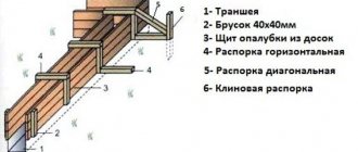
The formwork prepared for rectangular columns is a box of two pairs made of wood, metal or a combined panel material. The lateral pressure created by the concrete solution is compensated by clamps squeezing the box. Depending on the number of revolutions, clamps can be metal or wood.
The gaps left on the plates of metal clamps are necessary for wrapping columns of increased cross-section. The box is cleaned through a temporary hole prepared from the bottom of one formwork panel.
To attach the formwork panels to the reinforcement, tie bolts and ties are used. When preparing the formwork for low columns, it is secured in two perpendicular directions with steel cables. When installing columns with a height of 6-7 m, the formwork is connected to special scaffolding.
As soon as the formwork is installed, gaps of 50 × 50 cm are made every 200 cm in height, and areas are also equipped for concrete-laying work. Please note: the formwork of columns with a large height is installed only on three sides, while the remaining side is expanded when laying concrete.
Replacement of concrete columns
Depending on the purpose of using the columns, they can be replaced with the following materials:
- Square steel pipes (can be used in the construction of a one-story or two-story house, in the corners of the structure).
- Brick columns (it is not advisable to use if a large load is planned, since the material is less durable and may not withstand the weight of the structure).
- Wooden structures, which can be made of timber or logs (can be used in structures similar to a veranda or gazebo).
For almost all of these structures, as well as for the installation of concrete slabs, it is necessary to use a construction crane and involve several specialists.
It is worth noting once again that the process of pouring columns with concrete mixture is very labor-intensive, which means it is difficult to do it yourself. It requires great responsibility, skills and abilities to work with these materials. During the concreting process, it is necessary to follow many rules that were listed above.
Concreting columns with a circular cross-section
When installing round metal columns, mold blocks are prepared. To ensure optimal thickness of column protection, cement pads are used, secured to the steel frame bars with tying wire before laying the concrete.
Concreting of structures with a diameter of 40-80 cm in the absence of crossing clamps is carried out from above, without interruptions, in sections up to 500 cm high. Laying a mixture of columns with a cross-section of less than 40 cm, as well as when choosing structures of an arbitrary cross-section with provided overlapping clamps, is carried out from the side - in sections up to a height 2 m.
It is mandatory that breaks for shrinkage of the mixture are made at a significant height of column sections being concreted without preparing working joints. The duration of the break should be from 45 to 120 minutes.
Types of reinforced concrete columns
For the manufacture of reinforced concrete columns, heavy grades are used, most often M200 and M300, but M400 and M600 are also in demand under conditions of high loads. for products is also selected quite carefully; it is allowed to use stressed and unstressed metal reinforcement, from which a rigid frame is created inside. This provides the finished column with the necessary reliability, resistance to loads and deformations, and strength.
Today, manufactured reinforced concrete columns are divided according to various criteria. For example, according to the type of use, these can be columns without consoles and with consoles, divided into two-branch and rectangular.
The cross-section differs:
- square reinforced concrete columns;
- with a rectangular cross-section;
- round columns.
According to manufacturing features, all columns are divided into the following types:
- prefabricated technology (can be manufactured exclusively in specialized factory conditions);
- monolithic technology (manufacturing directly on the construction site using formwork is allowed).
Depending on the position of the reinforced concrete columns during installation, they differ:
- located on the facade of the building;
- located in the outer rows (corner and others);
- columns for the middle row.
Reinforced concrete columns according to type of use are divided into the following numerous groups:
- K - used for structures and structures without bridge supports.
- KS – columns for the installation of buildings and building structures with sagging lower chords.
- KKP - products used to construct the frame of a building.
- KF – reinforced concrete columns for the installation of half-timbered wall fencing (specialized columns, cannot be replaced by other types of products).
- KR - special frame columns used for the construction of buildings for various purposes, usually with small dimensions.
- KKS - columns used during the construction of buildings, structures for various purposes with sagging lower chords.
- KK are used for the construction of frame buildings with large areas and high load levels.
- KDP - columns for the construction of frames of large industrial buildings.
- KD are universal products for the construction of building frames for various purposes.
Reinforced concrete columns are the basis of capital construction and an important element in the construction of buildings. They are a supporting element in construction and are used in the manufacture of building frames along with crossbars, purlins and other elements.
The length of the reinforced concrete column is usually taken equal to the height of two floors of the building. Reinforced concrete columns are divided by type into:
T1 – fastening of a concrete console perpendicular to the main one; C1 – fastening of steel lattice connections; L1 – fastening of three-flight stairs; L – arrangement of two-flight staircases; P – support of the crossbars when the frame is rotated; SS - fastening of shear walls along two perpendicular, three or four faces of the columns; C – fastening of adjacent shear wall panels; T – fastening of fencing panels at the ends of the building.
According to their shape, the production of columns can be divided into: single-sided, double-sided, single-cantilever, double-console.
When marking columns, to describe all its qualities in a brand, approximately the following rule is used: columns series SK, length 4000 mm, width 200 mm, head width 450 mm, the first in load-bearing capacity (for trays 6 m long) - SK 40.2.5-1 GOST 23899-79.
Reinforced concrete columns are made only from reinforced concrete. The main requirements for all concrete mixtures for columns are: easy mixing, transportation, laying. Mixtures must have a certain hardening rate.
For reinforcement used in the production of reinforced concrete columns, a certain list of requirements is also imposed, such as high strength and plastic mechanical properties, strength and rigidity of adhesion to concrete, good weldability, low expansion in concrete, fatigue strength and corrosion resistance.
Columns of multi-storey buildings (GOST 18979-90) are made mainly in the form of rectilinear elements with a section of 300X300 and 400X400 mm, lengths of 1,2,3 and 4 floors. The most common are columns on two floors, up to 8.4 m long, weighing up to 3.5 tons. To support the crossbars, the columns have protruding consoles with a height of 150, 200 mm. At the ends of the columns there are outlets of longitudinal reinforcement. To ensure high-quality welding of reinforcement outlets during installation and reliable operation of column connections, special attention should be paid to the accuracy of the location of reinforcing bars during the manufacture of elements. Columns are made mainly from heavy concrete grades M200-M500. In cases of using lightweight structural concrete, its grade is assigned within the range of M200-M400. The columns are reinforced with spatial frames made of class A-III steel. Columns are manufactured using flow-unit and bench technology.
It is also possible to produce non-standard columns according to customer drawings.
Reinforced concrete columns are strong and reliable products in the form of vertically installed pillars, the length of which is much greater than the cross-section. Precast concrete columns are key components of a building structure and are used as building supports along with crossbars and purlins. They can be used with equal success for the construction of buildings with different numbers of floors. There is a wide range of standard sizes of columns, differing in dimensions, cross-sectional shape and type of reinforcement. All this is reflected in their mandatory labeling. Classification is made taking into account the technical characteristics of products. Reinforced concrete columns are superior in service life and strength to all other reinforced concrete structures used in construction. The higher the load-bearing capacity of the columns, the lower they are located in the building.
Laying concrete for frame structures
If the columns are elements of a frame structure, it is allowed to first concrete the columns and only then install the reinforcement.
When laying the concrete mixture on top at the first stage of work, the lower section of the formwork being installed is filled with cement mortar to only 10-20 cm. This is necessary to prevent the accumulation of coarse filler without the mixture at the base of the frame element.
In the process of pouring the first portion of the solution, the aggregate particles are enveloped in the mixture, and a material for concreting of normal composition is formed.
For compaction in solution columns, vibration-type devices equipped with flexible or rigid shafts are used. Pressing with external vibrators attached to the formwork of small-section columns is rarely used, as it has low efficiency.
To avoid sinkholes when laying a mixture of columns, the method of externally tapping the frame of the structure with a wooden hammer at a level slightly lower than or equal to the level of laying the mixture helps.
In accordance with the current SNiP, concreting of installed columns is carried out along the entire height of the structure without preparing working joints. Seams can only be located in the upper part of the foundation, at the top of crane beams, at the bottom of crane consoles, purlins.
Concreting of monolithic columns
TYPICAL TECHNOLOGICAL CARD (TTK)
CONCRECTING OF MONOLITHIC COLUMNS
1 AREA OF USE
1. A technological map (diagram) has been developed for the construction of monolithic columns.
2. Before starting work you must:
2.1. Prepare a set of panels for installation:
2.2. Clean the panels from debris and adhering cement mortar.
2.3. Check and accept according to the act all structures and their elements covered during the concreting process.
2.4. Lubricate the surface of the formwork with emulsion.
2.5. Make geodetic risks for the breakdown of column axes.
2.6. Prepare for work and check rigging, fixtures, and tools.
2.7. At the pre-assembly site, assemble the formwork in two parts.
Attention:
— The layout of the formwork panels when concreting the columns, the places and attachment points for the struts are indicated in the project developed by the owner of the formwork.
— When carrying out work in areas that do not have reliable fences, workers must be secured with a safety belt to avoid falling from a height. My fastening in each specific case is determined by the manufacturer of the work.
— All existing openings in the ceiling must be previously closed with shields secured against displacement and overturning.
2.8. Install the reinforcement frame of the column at the stage of reinforcing the grillages (or the floor below), align it and secure it to the outlets from the piles (or floor) using welding according to the design;
2.9. In the places where the column formwork struts are attached, install a block-anchor in two directions (as a block-anchor it is possible to use prefabricated reinforced concrete road slabs measuring 1.75x3.0 m); when making monolithic columns on a typical floor, to attach the struts, install mounting loops in the monolithic floor;
2.10. Install the formwork, align it using struts with a lanyard and secure it.
3. The concrete mixture is supplied to the laying site in bunkers by a crane or concrete pump.
4. To supply the concrete mixture into the column structure, it is necessary to provide receiving funnels.
5. The formwork is unslinged and the concrete mixture is unloaded by concrete slingers who are located on the inventory shed.
5.1. Workers are lifted to the site using a ladder.
6. When lifting, lowering and moving a concrete hopper, workers must be at ground level outside the danger zone.
6.1 Workers are lifted to the site only after the bunker with the concrete mixture is located above the unloading site at a height of no more than 1.0 m.
7. When carrying out work, it is necessary to follow the instructions of SNiP 3.03.01-87 “Load-bearing and enclosing structures” section 2 and SNiP 12-03-01 “Labor safety in construction”, SNiP 12-04-02 “Labor safety in construction” Part 2 .
2. ORGANIZATION AND TECHNOLOGY OF WORK EXECUTION
2.1. Technical readiness of work prior to concreting the columns.
Before concreting begins, the following work must be completed:
— temporary roads and access roads for construction equipment to the concreting area have been installed;
— temporary power supply and lighting are provided;
— mechanisms, equipment and devices were delivered and prepared;
— the horizontal surface on which concreting is carried out has been prepared;
— fittings and embedded parts were installed in accordance with the working drawings with the execution of an act for hidden work;
— formwork and scaffolding for the concrete workers performing the work were installed and accepted by the foreman.
2.2. Performers. Team composition of 3 people:
concrete worker of the IV category (B1)
Concrete worker of the 2nd category (B2, B3)
Note: Concrete workers working with a crane must have a slinger certificate.
2.3. Devices, equipment and tools.
Since concreting of vertical structures is carried out after reinforcement and installation of formwork, scaffolding means for workers receiving and laying concrete are used according to the decisions made for the previous stages of work.
The technology of reinforcement and formwork is adopted according to separate technological maps.
Scaffolding means can be:
- flooring with fencing on consoles fixed to the formwork or to buttresses for strengthening formwork panels (see, for example, solutions for self-supporting formwork systems).
- removable platforms or scaffolds (type LPU 4).
Carrying out concrete work from ladders is prohibited.
2.4. Organization of the workplace and description of operations:
— concrete worker B3 monitors the unloading of the concrete mixture from the body (Fig. 1) of the dump truck into the rotary hopper, being on the receiving platform. After unloading is completed, he, standing on the walls of the bunker, uses a shovel with an elongated handle to clean the body of the dump truck from the remains of concrete and pick up the crumbled concrete mixture after the vehicle has left.
Fig.1. Unloading concrete mixture from the body of a dump truck
— concrete worker B3 rigs a rotating bunker using lifting hinges. Having made sure that the sling is secure, he retreats to a safe zone. At the command of concrete worker B3, the crane operator delivers the bunker to the concreting site.
Fig.2. Slinging the rotating hopper using the lifting loops
— concrete workers B1 and B2, standing on the wooden scaffolding, take the rotating dispensing hopper (Fig. 3) with the concrete mixture, stopping its descent at a height of 1 m, and bring it to the unloading site. B2 holds the hopper with both hands, and B1 opens the gate and unloads the concrete mixture.
Fig.3. Reception of the dispensing rotary hopper with concrete mixture
If necessary, B1 turns on the vibrator installed on the hopper. Having made sure that the bunker is completely unloaded, concrete worker B1 closes the sector shutter with the handle upward, puts on the handle holder and gives a signal to the crane operator to move the bunker for loading (Fig. 4).
Fig.4. Scheme of supplying cargo to the workplace
— concrete workers B1 and B2 compact the laid layers (Fig. 5) of the concrete mixture with deep or surface vibrators (depending on the thickness and width of the concrete structure).
Fig.5. Compaction of laid layers of concrete mixture with deep or surface vibrators
At the same time, these same concrete workers use shovels to clean spilled concrete from the wooden flooring of the scaffolding and formwork, dumping it into the formwork of the concrete structure (Fig. 6).
Fig.6. Cleaning spilled concrete from wooden scaffolding and formwork with shovels
— concrete worker B3 accepts the empty dispensing hopper handed over by the crane driver, installs it on the concrete receiving platform and unfastens it.
— after laying the top layer of concrete mixture, concrete worker B2 smoothes the exposed surface of the concrete.
2.5. Basic instructions for organizing production
Concreting of structures should be carried out in accordance with the instructions of the main project and the requirements of SNiP 3.03.01-87 “load-bearing and enclosing structures”
Delivery and receipt of concrete mix
The composition of the concrete mixture, preparation, acceptance rules, control methods and transportation must comply with GOST 7473-94.
It is prohibited to add water at the site of laying the concrete mixture to increase its mobility.
Transportation and supply of concrete mixture should be carried out using specialized means that ensure the preservation of the specified properties of concrete. Concrete is delivered by dump trucks, concrete trucks or concrete mixer trucks with unloading into rotary bins.
Preparation for concreting
The concrete mixture should be laid on a prepared and cleared base, calibrated to the design level.
Immediately before concreting, the formwork must be cleaned of debris and dirt, and the reinforcement must be cleaned of loose rust. The cracks in wooden, plywood and metal formwork should be coated with lubricant, and the surfaces of concrete, reinforced concrete and reinforced cement formwork should be moistened. The surface of previously laid concrete must be cleaned of cement film and moistened or covered with cement mortar.
Supply and placement of concrete mixture.
Concrete mixtures should be laid in horizontal layers of equal thickness (~0.3x0.5 m) without breaks, with the laying direction in the same direction in all layers. Laying the next layer of concrete mixture must be done before the concrete of the previous layer begins to set. The top level of the laid concrete mixture should be 50x70mm below the top of the formwork panels.
Get full text
The permissible height for free dropping of the concrete mixture is taken according to table 2 of SNiP 3.03.01-78. At a higher height of dropping the mixture, in order to avoid its stratification, its descent into the columns should be carried out along vibrating chutes, inclined trays or chutes, ensuring slow sliding of the mixture into the formwork.
Laying concrete mixture without working joints is permitted under the following conditions:
— concreting walls in tiers not exceeding 3 m;
— concreting columns with a cross-section of more than 0.4x0.4 m to a height of up to 5 m;
— concreting columns with a cross-section of less than 0.4x0.4 m and columns of any cross-section with intersecting clamps to a height of up to 2 m.
For areas at higher altitudes that are concreted without working joints, it is necessary to arrange breaks to allow the concrete mixture to settle. The duration of the break to ensure the settlement of the laid concrete is established by the construction laboratory - it must be at least 40 minutes, but not exceed 2 hours.
When organizing working joints, their surface must be perpendicular to the axis of the columns being concreted. Working joints (by agreement with the design organization) may be installed during concreting:
- columns at the marks of the top of the foundation, the bottom of the girders of beams and crane consoles, the top of crane beams, the bottom of column capitals.
During the concreting process and upon completion, take measures to prevent adhesion of plugs, formwork elements and temporary fastenings to the concrete
Compaction of concrete mixture
The concrete mixture is compacted by vibration using deep vibrators. The step of rearrangement of deep vibrators should not exceed 1.5 of their radius of action. The maximum thickness of the laid layer should not exceed 1.25 times the length of the working part of the vibrator, and when the vibrator is positioned at an angle of up to 35°, the thickness of the layer should be equal to the vertical projection of its working part. The depth of immersion of the vibrator into the concrete mixture should ensure its deepening into the previously laid layer.
Find out the cost of your work
Free order evaluation!
In places where reinforcement, embedded products or formwork prevent proper compaction of the concrete mixture by vibrators, it should be additionally compacted by jointing.
When compacting the concrete mixture, it is necessary to ensure that the vibrators do not come into contact with the frame reinforcement. It is not allowed to rest vibrators on reinforcement, embedded products, ties and other formwork fastening elements.
Curing and maintaining concrete
During the hardening period, concrete must be protected from precipitation or moisture loss. Subsequently, maintain the temperature and humidity conditions to create conditions that ensure an increase in its strength.
When concreting structures in winter, measures for the care of concrete, the order and timing of their implementation, control over their implementation and the timing of stripping of structures must be established by the PPRk.
The movement of people on concreted structures and the installation of formwork on overlying structures is allowed after the concrete reaches a strength of at least 15 kg/cm.
2.6. Features of laying concrete mixture during the construction of columns (Fig. 7)
Fig.7. Laying concrete mixture in columns:
a - columns up to 5 m high; b - the same, more than 5 m high; c - the same, with thick reinforcement; d - diagram of formwork with a removable panel; 1 - formwork; 2 - clamp; 3 - tub; 4 — vibrator with a flexible shaft; 5 — receiving funnel; 6 — link trunk; 7- mounted vibrator; 8, 9 — pockets; 10 — removable shield
In columns up to 5 m high with cross-sectional sides up to 0.8 m, which do not have intersecting clamps, the concrete mixture is laid immediately to the entire height. The mixture is carefully loaded from above and compacted with internal vibrators (Fig. 7, a). When the height of the columns is over 5 m, the mixture is fed through funnels along the trunks (Fig. 7, b). In tall and densely reinforced columns with intersecting clamps, the mixture is laid in tiers up to 2 m with loading through windows in the formwork or special pockets (Fig. 7, c). Sometimes, to supply the concrete mixture, column formwork is made with removable panels (Fig. 7, d), which are installed after concreting the lower tier.
3. REQUIREMENTS FOR THE QUALITY OF WORK PERFORMANCE
Quality control and acceptance of structures
3.1. A log of concrete work must be kept on site every shift.
3.2. When accepting concrete structures, in accordance with the requirements of current state standards, determine:
- quality of concrete in terms of strength, and, where necessary, frost resistance, water resistance and other indicators specified in the project;
— quality of surfaces;
— presence and compliance with the design of holes, openings and channels;
— presence and correct execution of expansion joints;
— permissibility of design deviations according to Table 11 of SNiP 3.03.01-87*, in particular:
| Parameter | Limit deviations |
| 1. Deviation of the lines of the intersection planes from the vertical or the design slope to the entire height of the structures for: | |
| columns supporting monolithic coverings and floors | 15 mm |
| columns supporting precast beam structures | 10 mm |
| 2. Deviation of horizontal planes over the entire length of the area being verified | 20 mm |
| 3. Local unevenness of the concrete surface when checking with a two-meter strip, except for supporting surfaces | 5 mm |
| 4. Length or span of elements | ±20 mm |
| 5. Cross-sectional size of elements | +6 mm; 3 mm |
| 6. Markings of surfaces and embedded products that serve as supports for steel or precast concrete columns and other precast elements | 5 mm |
| 7. Slope of the supporting surfaces of foundations when supporting steel columns without grout | 0,0007 |
| 8. Location of anchor bolts: | |
| inside the support contour | 5 mm |
| in terms of outside | 10 mm |
| in height | +20 mm |
| 9. Difference in height marks at the junction of two adjacent surfaces | 3 mm |
Documents (invoices, certificates, acts for hidden work, etc.) must be submitted confirming the quality of the materials, products and semi-finished products used.
3.3. Acceptance of completed concrete and reinforced concrete structures or parts of structures should be documented with an inspection report for hidden work or an acceptance report for critical structures.
Quality control and acceptance of concrete
1. Quality control of concrete work involves its implementation at the following stages:
- preparatory;
— concreting (preparation, transportation and laying of concrete mixture);
— curing concrete and stripping structures;
— acceptance of concrete and reinforced concrete structures or parts of structures.
2. At the preparatory stage it is necessary to control:
— the quality of the materials used for preparing the concrete mixture and their compliance with GOST requirements;
— readiness of concrete mixing, transport and auxiliary equipment for concrete work;
— the correct selection of the composition of the concrete mixture and the purpose of its mobility (rigidity) in accordance with the instructions of the project and the conditions of work;
— test results of control concrete samples when selecting the composition of the concrete mixture.
3. The composition of the concrete mixture must be selected by a construction laboratory. The composition, preparation, transportation and laying of the concrete mixture, the rules and methods for controlling its quality must comply with GOST 7473-94 and the requirements of Table 1. The composition of the concrete mixture during the work process must be adjusted taking into account the changing characteristics of the source materials (binders, fillers).
Table 1
| Technical requirements | Permissible deviations | Control (method, volume, type of registration) |
| 1 | 2 | 3 |
| 1. Number of fractions of coarse aggregate with grain size, mm: up to 40; St.40 | At least two At least three | Measuring, according to GOST 10260-82, work log |
| 2. Largest aggregate size: for reinforced concrete structures; for slabs; for thin-walled structures; when pumping with a concrete pump; including grains of the largest size, flakie and needle-shaped | No more than 2/3 of the smallest distance between reinforcement bars No more than 1/2 the thickness of the slabs No more than 1/3-1/2 the thickness of the product No more than 0.33 of the internal diameter of the pipeline No more than 15% by weight | Same |
| 3. When pumping through concrete pipelines, the content of sand with a particle size of less than, mm 0,14 0,3 | 5-7% 15-20% | Measuring, according to GOST 8736-93 |
4. Transportation of the concrete mixture must be carried out using specialized means provided for by the PPR.
The accepted method of transporting concrete mixture should:
— exclude precipitation and direct exposure to sunlight;
— eliminate delamination and violation of homogeneity;
- prevent loss of cement laitance or mortar.
5. The maximum duration of transportation of the concrete mixture should be established by the construction laboratory with the condition of ensuring the preservation of the required quality of the mixture during the journey and at the place of its placement.
6. Before laying the concrete mixture, the foundations (soil or artificial), the correct installation of formwork, reinforcement structures and embedded parts must be checked. Concrete bases and working joints in concrete must be thoroughly cleaned of cement film without damaging the concrete, formwork - from debris and dirt, reinforcement - from rust deposits. The internal surface of the inventory formwork must be coated with a special lubricant that does not impair the appearance and strength qualities of the structures.
7. During the process of laying the concrete mixture, it is necessary to control:
— condition of scaffolding, formwork, position of reinforcement;
— quality of the mixture being laid;
— compliance with the rules for unloading and distribution of concrete mixture;
— thickness of the layers being laid;
— mode of compaction of the concrete mixture;
— compliance with the established concreting procedure and rules for constructing working joints;
— timeliness and correctness of sampling for the production of control samples of concrete.
The control results must be recorded in the concrete work log.
8. Quality control of the concrete mixture being laid should be carried out by checking its mobility (rigidity):
- at the place of preparation - at least twice per shift in conditions of stable weather and constant humidity of the aggregates;
- at the installation site - at least twice per shift.
9. The supply and distribution of the concrete mixture must be carried out in accordance with the PPR (chutes, trunks, vibrating trunks, buckets, belt conveyors, concrete pumps, etc.). When supplying concrete mixture by any method, it is necessary to prevent separation and leakage of laitance.
10. The concrete mixture must be laid in structures in horizontal layers of equal thickness, without breaking, with a consistent direction of laying in one direction in all layers. The thickness of the laid layer should be set depending on the degree of reinforcement of the structure and the compaction means used.
11. When compacting the concrete mixture, it is not allowed to rest vibrators on reinforcement and embedded products, ties and other formwork fastening elements. The depth of immersion of the deep vibrator into the concrete mixture should ensure its deepening into the previously laid layer by 5-10 cm. The step of rearranging the deep vibrators should not exceed one and a half radius of their action. The step of rearranging the surface vibrators should ensure that the vibrator platform overlaps the border of the already vibrated area by 100 mm.
12. Laying the next layer of concrete mixture is allowed before the concrete of the previous layer begins to set. The duration of the break between laying adjacent layers of concrete mixture without forming a working joint is established by the construction laboratory. The top level of the laid concrete mixture should be 50-70 mm below the top of the formwork panels.
Get full text
13. The surface of the working joints made when laying the concrete mixture intermittently must be perpendicular to the axis of the columns and beams being concreted, to the surface of the slabs and walls. Concreting may be resumed once the concrete reaches a strength of at least 1.5 MPa.
Working joints, in agreement with the design organization, may be installed during concreting:
- columns - at the level of the top of the foundation, the bottom of the purlins, beams and crane consoles, the top of the crane beams, the bottom of the column capitals.
14. When laying and compacting the concrete mixture, the requirements of Table 2 must be observed.
table 2
| Technical requirements | Permissible deviations | Control (method, volume, type of registration) |
| 1 | 2 | 3 |
| 1. Strength of surfaces of concrete foundations when cleaning from cement film, MPa, not less: with water and air jets; mechanical wire brush; hydrosandblasting or mechanical cutter | 0,3 1,5 5,0 | Measuring, according to GOST 10180-90, GOST 18105-86, GOST 22690-88, work log |
| ________________ Instead, GOST R 53231-2008 applies. — Note from the database manufacturer. | ||
| 2. Height of free dropping of concrete mixture into the formwork of structures, m, not more than: | Measuring, 2 times per shift. work log | |
| columns | 5,0 | |
| 3. Thickness of the laid layers of concrete mixture: when compacting the mixture with heavy suspended vertical vibrators; when compacting the mixture with suspended vibrators located at an angle (up to 30%) to the vertical; | 5-10 cm less than the length of the working part of the vibrator Not more than the vertical projection of the length of the working part of the vibrator | Measuring, 2 times per shift, work log |
| when compacting the mixture with manual deep vibrators; when compacting the mixture with surface vibrators in structures: unreinforced; with single fittings; with double fittings | No more than 1.25 times the length of the working part of the vibrator 40 25 12 |
15. The composition of measures at the concrete curing stage, its care and the sequence of stripping of structures is established by the PPR in compliance with the following requirements:
— maintaining temperature and humidity conditions that ensure an increase in the strength of concrete at a given pace;
— prevention of significant temperature-shrinkage deformations and crack formation;
— protecting hardening concrete from impacts and other mechanical influences;
— protection during the initial period of concrete hardening from precipitation or loss of moisture.
16. The movement of people along concreted structures and the installation of formwork of overlying structures on them is allowed after the concrete reaches a strength of at least 1.5 MPa.
17. Stripping concrete structures is allowed when the concrete reaches strength.
18. Defective areas of the surface discovered after stripping (gravel surfaces, sinkholes) must be cleared, washed with water under pressure and rubbed (sealed) with a cement mortar of composition 1:2-1:3.
19. Concrete quality control involves checking the compliance of the actual strength of concrete in the design with the design and specified during intermediate control, as well as frost resistance and water resistance with the requirements of the project.
20. When checking the strength of concrete, compression tests of control concrete samples are mandatory.
Control samples must be made from concrete mixture samples taken at the site of its preparation and directly at the site of concreting structures (for strength testing). At the concreting site, at least two samples must be taken per day during continuous concreting for each concrete composition and for each group of structures being concreted. One series of control samples (at least three samples) must be prepared from each sample.
Testing of concrete for water resistance and frost resistance should be carried out using samples of the concrete mixture taken at the place of preparation, and in the future - at least once every 3 months and when the composition of the concrete or the characteristics of the materials used change.
21. The results of concrete quality control must be reflected in the journal and work acceptance certificates.
4. MATERIAL AND TECHNICAL RESOURCES
List of main machines, mechanisms, devices and equipment (Table 3)
Table 3
| N p.p. | Name | Brand and parameters | Unit change | Quantity | Note |
| 1 | Rotary hopper | BP-0.5 | PC. | 3 | GOST 21807-76* |
| Rotary hopper | BP-1.0 | PC. | 3 | GOST 21807-76* | |
| 2 | Sling 4 branches | 4sk1-8.0/5000 4sk-8.0/5000 | PC. | 2 | GOST 25573-82 RD 11-07-2007 |
| 3 | Universal sling | USK 1-3.2/6000 | PC. | 2 | RD 11-07-2007 |
| ________________ RD 11-07-2007 is invalid. — Note from the database manufacturer. | |||||
| Sling 2(x) loop | SKP1-3.2/6000 | PC. | 1 | GOST 25573-82 | |
| 4 | Vibrator for compacting concrete mixture | IV-66 Day=38 (deep) | PC. | 2 | Catalog TsNIIOMPT |
| Vibrator for compacting concrete mixture | IV-47A Day=76 (deep) | PC. | 2 | Catalog TsNIIOMTP | |
| Vibrator for compacting concrete mixture | IV-92 (surface) | PC. | 2 | Catalog TsNIIOMTP | |
| Vibrator for compacting concrete mixture | SO-131A (vibrating screed) | PC. | 1 | Catalog TsNIIOMTP | |
| 5 | Machine for smoothing concrete surfaces | SO-135 | PC. | 1 | Catalog TsNIIOMTP |
| 6 | Reception tray | V2.0m | PC. | 1 | GOST 21807-76* |
| 7 | Lighthouse batten | PC. | 2 | inv. | |
| 8 | Lath 2(x) m. with level | PC. | 1 | TsNIIOMTP r. part 3295.10.000 | |
| 9 | Universal rule | PC. | 2 | Catalog TsNIIOMTP | |
| 10 | Steel trowel for construction | PC. | 2 | GOST 10403-80* | |
| ________________ * Lost force in the Russian Federation without replacement. — Note from the database manufacturer. | |||||
| 11 | Steel construction shovel | LP/LR | PC. | 2/2 | GOST 3620-76 |
| 12 | Mechanical brush | PC. | 1 | inv. | |
| 13 | Construction helmet | PC. | 3 | GOST 12.4.087-84 | |
| 14 | Safety belt | PC. | 2 | GOST R 50849-96 | |
| 15 | Safety rope | PC. | 1 | GOST 12.3.107-83 |
5. SAFETY INSTRUCTIONS
1. Concreting the structures of buildings and structures should be carried out in compliance with the requirements of SNiP 12-03-2001 “Labor safety in construction”, SNiP 12-04-2002 “Construction production” part 2, job descriptions and PPRk.
2. Every day before starting to place concrete in the formwork, it is necessary to check the condition of the container, formwork and scaffolding. Detected malfunctions should be corrected immediately.
3. Before starting to lay the concrete mixture with a vibrating robot, it is necessary to check the serviceability and reliability of fastening all the links of the vibrating robot to each other and to the safety rope.
4. Rotating bunkers (tubs) for concrete mixture must satisfy GOST 21807-76.
5. Movement of a loaded or empty hopper is permitted only when the gate is closed.
6. When laying concrete from buckets or bunkers, the distance between the lower edge of the bucket or bunker and the previously laid concrete or the surface on which the concrete is laid should be no more than 1 m, unless other distances are provided for in the work design.
7. The opening of the bunker is carried out by the concrete worker after the crane boom has stopped and while not under the bunker and the crane boom. Unloading of containers by weight should be carried out evenly for at least 5 seconds.
8. Instant unloading of containers by weight is prohibited.
9. Workers laying concrete mixture on surfaces with a slope of more than 20 must use safety belts.
10. When compacting a concrete mixture with electric vibrators, it is not allowed to move the vibrator by the current-carrying hoses, and during breaks in work and when moving from one place to another, the electric vibrators must be turned off.
11. Special conditions for ensuring safe work during steam and electric heating, the use of chemical additives, etc. must be resolved as part of the PPR.
12. It is prohibited for concrete workers to cross scaffolding means that are not secured in the design position and do not have a fence or safety rope.
13. In each shift, constant technical supervision must be provided by foremen, foremen, foremen and other persons responsible for the safe conduct of work. Monitoring the good condition of stairs, scaffolding and fences, as well as the cleanliness and sufficient lighting of work areas and passages to them, the presence and use of safety belts and safety helmets.
The electronic text of the document was prepared by Kodeks JSC and verified against the author’s material. Author: - Ph.D., teacher of the Military Engineering and Technical University, St. Petersburg, 2005
Features of concreting frame structures
When preparing frame-type structures, breaks must be taken between laying concrete for columns and frame crossbars. In this case, the working seams will be placed 1-2 cm above/below the border where the frame crossbar is attached to the frame.
Walls, including partitions, can have a changing or constant cross-section. Such structural elements are inclined, vertical, curved, round, straight, and also polygonal.
For concreting partitions, formwork is usually used using standard panels, block forms, panel elements of collapsible formwork, etc.
Installation of the most popular collapsible formwork is carried out in two stages. At the first stage, the formwork is mounted on one side to the height of the equipped partition; in the second stage, it is installed after attaching the metal frame and on the other side.
Thus, concreting columns has a number of features depending on the shape of the section, the height of the structure and other factors. If the basic rules for laying the mixture are violated, the operational parameters of the frame element will be significantly reduced.
