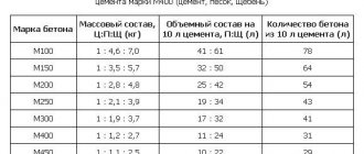
Well cement is one of the types of structural materials. This is a type of Portland cement. The material is intended for the construction and construction of various wells, for example, for the extraction of natural liquid fuel sources from groundwater pressure.
Composition and features
Well cement is a binder composition that is almost indistinguishable from Portland cement. However, there are increased requirements for clinker content. In cementing, the proportion of clinker can reach 100%. The required admixture is up to 3.5% ground gypsum.
To improve the properties of the material, you can supplement it with various mineral elements, which in total will amount to no more than 12% of the total mass. There should be no more than 10% limestone, slag - up to 20%.
The conditions, standards of substances and purpose for cement cement are recorded in GOST 1581. The type of substances is determined by the percentage of refractory admixtures and other components. The recipe for ready-made cement may vary depending on the manufacturer.
Features of well cement:
- fine grind;
- accelerated hardening process;
- increased mechanical strength and rigidity;
- when diluted with water, the consistency differs from that of other types of cement.
There are increased requirements for the fluidity rate in building codes and regulations. The speed of movement of the cement solution should reach 1.5 m/s with small sizes of technological holes. Due to the extremely high pressure in places where this composition is used, sand, reinforcement, formwork, and crushed stone are not added. Therefore, the binder is the only component.
The peculiarities of the use of such a composition determine high requirements for it as a building material. It should reduce the pressure exerted on the pipeline or other part that is being insulated. In addition, the cement slurry must have a higher solidification rate, which is achieved by introducing various additives during manufacturing.
Grouting of horizontal wells
Plugging of horizontal wells is carried out much less frequently. They have a more complex structure, as they include elements of vertical and inclined structures. In economic terms, the installation of horizontal wells is 3-4 times more expensive than vertical ones, therefore, the technology of plugging horizontal pipes should ensure maximum reliability of the cement “jackets” of the casing columns and the duration of operation of the mine. For it to be profitable, the income from production must exceed the funds invested in its creation.
Main technical characteristics
These will depend on the type of binder, the manufacturer and the presence or absence of additives.
Performance characteristics:
- Mechanical strength after 8 hours reaches 2.1-10.3 MPa, depending on temperature. The maximum value is observed at 60 °C.
- Bending rigidity varies in the range of 0.7-3.5 and depends on the manufacturer and brand.
- Residual weight on a sieve with mesh No. 0.08 is no more than 15%.
- Specific surface – no more than 270 m²/kg.
- The moisture separation index should not exceed 10.
- Spreadability under the influence of moisture varies depending on the type. Unplasticized cement cement can spread at a speed of up to 200 mm. Plasticized - up to 220.
- The composition hardens to a consistency of 30 in 90 minutes or more.
All characteristics must be indicated in the manufacturer's mark along with information about the production date. Portland cement loses its properties after six months or when exposed to air.
The rate of solidification will depend on the temperature in the well and the percentage of alkaline substances in the composition. If the temperature exceeds 60 °C, the hardening time may vary.
Checking for compliance with GOST
According to GOST 26798.1-96, the parameters of drilling fluids are determined without taking into account possible impacts that may occur during the operation of the material in real conditions with the connection of casing strings. The thickening time of the mixture, density and viscosity are checked for compliance with standards. At the same time, for different compositions, both technical indicators and the list of evaluation criteria may change. Thus, to determine the expansion properties and strength in the case of cement mortar, GOST 1581-96 is used, which requires that tests be carried out at an ambient temperature of about +30 °C. During the process of hardening of cement stone mixtures in a limited volume, strength indicators can be higher than when using a mass of similar composition when filling a well. And, on the contrary, the permeability of the solution decreases.
Classification of cement cement mixtures
All requirements for this type of cement are standardized according to GOST. There are several types of cement depending on their characteristics.
According to density indicators, 2 types are conventionally distinguished:
- Light type - normal mixture.
- Weighted, containing impurities that increase mass.
Depending on the temperature regime, there are the following types:
| Nomenclature name | Temperature range, °C |
| Low and normal | 15-50 |
| Moderate | 51-100 |
| Elevated | 101-150 |
Types of compositions according to the degree of resistance of substances to chemicals contained in groundwater:
- without increased stability;
- resistant to sulfates, including special additives.
Classification.
For some types, there are 2 levels of sulfate resistance: moderate and increased.
According to the condition of the cement paste, the material is divided into:
- Unplasticized;
- Hydrophobized.
Underwater concreting
Preparing the base for the foundation
After completing the development of a dry pit, immediately before starting to lay concrete, the bottom of the pit must be cleaned to the design level.
In the case of excavation excavation with drainage, its bottom is leveled, the dimensions are checked and, if necessary, the base is compacted. To do this, a layer of gravel or crushed stone 10-15 cm thick is poured into the bottom and compacted.
For wet clay soils, a layer of crushed stone at least 10...15 cm thick should be compacted into the base, previously cleared of the upper liquefied layer, and poured with cement mortar.
If keys are found at the bottom of the pit, they must be plugged, and if this fails, it is necessary to arrange a dig with water drainage outside the foundation. Coptage is a structure (riprap, well, trench) for intercepting and collecting groundwater in places where it is brought to the surface ( see Fig. ).
In foundation pits for medium and large bridges, especially with statically indeterminate span systems, the soils in the foundations must be tested and control drilling carried out to check the actual thickness of the bearing layer.
If the soil in a water-filled pit was excavated without drainage, then in order to be able to pump water out of the pit, before concreting the foundation, it is necessary to lay a grouting layer of concrete using the underwater concreting method. Due to its qualities, cement concrete usually cannot be an integral part of the foundation structure, so it must be placed below the design level of the base of a low pile grillage, and the depth of the pit must be increased accordingly.
When constructing foundations, careful control of all hidden work is necessary, i.e. checking the condition and density of the soil at the bottom of the pit, the absence of cavities in the concrete masonry, it is necessary to test concrete samples from various parts of the foundation, etc.
Underwater concreting is used in foundation construction both for constructing a grouting layer in pits and for erecting drilled piles, filling shell cavities and connecting them with rocks, and filling shaft openings in subsidence wells.
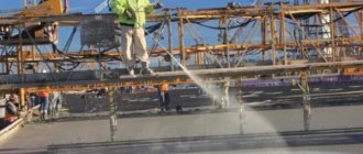
For underwater concreting, the vertically moved pipe (VPT) method is most widely used. When technological operations are carried out carefully, it ensures dense, uniform and sufficiently strong masonry, as well as high productivity.
When working using the VPT method, concrete is concreted using vertically suspended pipes, which are gradually moved upward as the concrete mixture comes out of them. The pipes are installed at a distance from one another, taking into account the mixture spreading area. From one pipe, the mixture spreads over a radius of 2 to 4 m, depending on the consistency, depth of the pit and pipe diameter. The concrete mixture must be plastic with a cone draft of 16-20 cm, the flow rate through each pipe is usually 3...20 m 3 / h, depending on the mobility of the mixture and the depth of the pit.
Inventory concrete pipes are steel pipes with a diameter of about 300 mm, made up of sections 2–5 m long with flanged connections. A funnel with a volume of 1 - 3 m3 is attached to the top of the pipe on the flanges. Funnels with pipes are suspended on a specially provided beam cage.
Rice. Scheme of underwater concreting using the VPT method: 1 – floating crane for supplying concrete mixture, 2 – dispensing hopper, 3 – concrete pipe, 4 – laid concrete mixture, 5 – formwork, 6 – sheet piling
The adhesion of the grouting concrete layer to the walls of the pit made from metal inventory piles should be prevented. For this purpose, the metal tongue is coated with bitumen or other lubricant.
To ensure the quality of underwater concrete, it is necessary to prevent the possibility of water entering the concrete pipe. To do this, the lower end of the pipe, when lifting it, must always remain buried in the laid layer of the mixture, and when initially filling the pipe, protective devices are required in the form of plugs (plugs), which gradually lower to the bottom of the pipe as it is filled with concrete mixture. The plug is supported by a wire passed inside the pipe. After filling the pipe with the mixture, the wire is cut.
The concrete mixture will move through the pipe and exit if its weight becomes greater than the hydrostatic pressure at the bottom of the pipe and the frictional forces against the pipe walls. This condition is ensured by the corresponding excess of the funnel above the water level in the reservoir. The excess of the funnel above the water is determined by the formula:
where r
– radius of the pipe;
H
– water depth.
For a negative value of h
, the excess of the funnel can be taken at any convenient level according to the concreting conditions.
The movement of concrete mixture through pipes is facilitated by vibrating the funnel and pipe with mounted vibrators. The mixture is laid, as a rule, without interruptions. During forced breaks, laying the concrete mixture is resumed only after the concrete reaches a strength of 2.5...3 MPa.
The thickness of the cement layer is determined from the condition of equality of the weight of the concreted slab and the hydrostatic pressure at the level of the bottom of the pit with a safety factor of 1.1. In all cases, the minimum layer of underwater concrete must be at least 1 m
The height of the concrete masonry erected underwater is adjusted 15-20 cm above the design level of the backfill pad. Excess volume of masonry, consisting of sludge, is removed to the design level after pumping out the water. Water pumping begins after the concrete of the backfill layer gains a strength of 5 MPa
93.79.221.197 © studopedia.ru Not the author of the materials posted. But it provides the opportunity to use it for free. Is there a copyright violation? Write to us | Feedback.
Disable adBlock! and refresh the page (F5)
very necessary
Marking and its decoding
Each type of well cement has its own nomenclature name, which corresponds to its properties.
The cement marking consists of 5 symbols:
- PCT - Portland cement cement.
- Type of binder and mark on lightweight or weighted composition.
- The third numerical value corresponds to the strength level of the product. This indicator is determined by the manufacturer.
- The next number determines the temperature level and the condition of the cement paste. For example, 150-PL - for working with elevated temperatures. Plasticized dough.
- The last mark is the regulatory act to which the manufactured product complies.
Marking.
Additives for improving cement slurries
To improve the performance of the solution, you can use additional additives:
- Calcium chloride and sodium carbonate speed up the setting time of cement. When added to a liquid, a quick-setting mixture is obtained and can be used at temperatures up to 65 °C. For expansion properties, up to 30% gypsum-alumina cement is added.
- If you add gypsum, the hardening time is significantly reduced, as a result, a stone with increased strength is formed 3-4 hours after injection of the solution. To prevent solidification in the drills themselves, process inhibitors are added.
- Bentonite increases the initial mobility of the solution, which is especially important when pumping it.
- Compositions containing clay additionally improve the viscosity of the material during its extrusion, which allows for subsequent hardening of the solution with increased plastic strength.
- A cement-resin composition with the addition of plastic substances, mainly epoxy aliphatic resins, is used if aquifers are located near the well.
- If it is necessary to pump the solution to a depth of more than 100 m, diesel fuel is added. The cement is completely inert to organic hydrocarbons, and the solution becomes much more viscous. Strength is gained after hydrocarbons are replaced by water.
When is packing necessary?
Before making a project, the decision on plugging is made based on the following signs:
Water well drilling technology
- The quality of water in the water intake structure has deteriorated. In this case, restoration measures will not give the desired effect or are generally impractical.
- The well's flow rate has decreased to a minimum, and it is no longer in operation.
- Small temporary waterworks are no longer needed as water is now supplied from a different source.
- According to the act, irreparable defects were discovered in the design, which led to a deterioration in water quality or a decrease in water intake productivity. The same is done if eliminating defects is not profitable for economic reasons.
- Sometimes, according to the project, test geological exploration or prospecting wells are carried out. After receiving the necessary information, they must be tamponed.
- The flowing well is no longer in operation.
- If absorption wells threaten to contaminate other aquifers, they are plugged.
Technology and scope
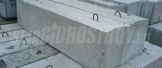
This type of cement is not used in the construction of residential buildings because it hardens too quickly. Such concrete blocks are mainly used in oil and gas wells. The solution can be used for pouring piles in difficult conditions.
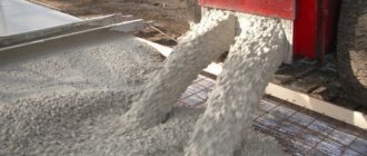
It is filled entirely with water using special pumps, the liquid is added to the composition in a ratio of 2:1. Then, when the cement becomes a flexible dough (this state is called "pulp"), it can be pumped into the hole. After complete hardening, the material becomes monolithic and reliably protects from groundwater.
Method of laying a cement layer in a pit fenced with sheet piles
The invention relates to the field of construction, and in particular to laying a cement layer in a sheet piling.
The technical result is an improvement in the quality of the cement layer and a reduction in the amount of concrete in the cement layer. A bunker with a concrete pipe and a closed waterproof shutter is loaded with concrete from a concrete mixer, the bunker is moved into a sheet piling to the place where concreting needs to be done, and the concrete pipe is installed with the shutter on the ground. After this, the shutter will be unlocked. Raise the bunker with the concrete pipe to a height of 0.5-0.6 of the pipe diameter and place a portion of the concrete mixture equal to the volume of the bunker in the desired location. After laying a portion of the concrete mixture, the bunker with the concrete pipe is removed, the waterproof shutter is closed and the bunker is loaded with concrete mixture, after which the process is repeated. 5 ill. The invention relates to the field of construction and can be used in transport and hydraulic engineering construction, for example, when laying a cement layer of underwater concrete in the construction of bridge supports, foundations for lighthouses, etc. in sheet piling.
There is a known method of laying underwater concrete using the method of vertical pipe movement (VPT), consisting of lowering a concrete pipe, in the lower part of which an opening and closing valve is installed, installing a plug inside the pipe and supplying the concrete mixture into the concrete pipe. By adjusting the degree of opening of the valve, the concrete mixture, following the plug, gradually falls down and is released through the lower end of the pipe onto the surface of the underwater soil. For further concreting, it is necessary to lift the pipe and perform concreting in height /JP, 60-498, E 02 D 15/06, 1985/.
The disadvantage of this method is that the valve is located at some distance from the end of the concrete pipe and water and soil enter the concrete mixture. This leads to heterogeneity of the concrete being placed.
There is a known method of laying underwater concrete in casing pipes using a concrete-cast pipe having a waterproof seal at the bottom.
The method is as follows.
A hopper with a concrete pipe is loaded with concrete, the end of which is hermetically sealed with a shutter, then the concrete mixture is compacted in the concrete pipe with a vibrator and the shutter is opened. Then the concrete pipe is lowered to the bottom of the structure being concreted and raised to a height of 10-15 cm, the vibrator is turned on and the concrete is laid. Subsequent filling of the concrete pipe with a concrete mixture and with its leader lifting, concreting is carried out using the method of vertical lifting of the pipe /VPT method/ /SU, 392208, E 02 D 15/07, 1971/.
The disadvantage of this method of VPT is that in order to achieve uniformity of the concrete mixture being laid, it is necessary to permanently position the end of the pipe in the previously laid concrete.
When concreting, for example, cast-in-place piles, this method is widely used. But when concreting large areas, the installation of several such devices is required to ensure continuity of the cement layer. But in this case, the exact dosage of the concrete mixture is not guaranteed.
The closest to the described invention in terms of technical essence and achieved result is the method of laying a cement layer, which consists in installing a transverse bridge on top of a sheet pile fence with several bunkers with concrete pipes located on it, the lower end of which is blocked by a gate. With the gate valves open, the grouting layer is concreted until the design mark of the concrete under the bridge is reached by pouring concrete from each pipe, with its lower end placed in the poured concrete, after which the bridge is remounted to the next concreting strip / Kosterin E.V. Foundations and foundations. M. Higher School, 1978, p. 124-126, fig. 5.13/.
The disadvantage of this method is the bulkiness of the structure, the difficulty of obtaining a flat surface of the grouting layer and the need to use concrete of high plasticity to cover a large concreting area, which reduces the strength of the concrete being laid.
The technical result of the proposal is a reduction in metal consumption, possible precise dosage at any point in the concreting area, an increase in the strength of the concrete being laid by increasing the rigidity of the concrete mixture, and eliminating the need to shift the previously laid concrete mass. In addition, the need for continuity of concreting, associated with the need to bury the concrete pipe into previously laid concrete, is eliminated. The technical result is achieved due to the fact that in the method of laying a grouting layer in a pit fenced with sheet piles, which includes underwater laying of concrete on the bottom of the pit in separate sections by installing at the bottom of the pit a bunker loaded with concrete with a concrete pipe attached to it, the lower end of which is blocked by a shutter with flaps , the lifting of the pipe with the simultaneous pouring of concrete from it with the valve flaps open and with the placement of the lower end of the pipe in the poured concrete is carried out to a height equal to 0.5-0.6 of its diameter, and the pouring of concrete is carried out in a volume equal to the volume of the bunker , and after pouring the concrete, remove the pipe from the pit with the shutter doors closed, fill the bunker with concrete and move the pipe to the next concreting site.
The essence is illustrated by drawings, which show: in Fig.1 loading of a concrete pipe with a closed waterproof shutter, in Fig.2 - installation of a concrete pipe in a sheet piling on the ground; figure 3 - lifting the concrete pipe by 0.5-0.6 of its diameter and laying a portion of the concrete mixture; in fig. 4 laying concrete mixture on the next section of the pit; Fig.5 shows a waterproof shutter.
A concrete mixer 2 is installed on the floating support 1, which loads a hopper 3 with a concrete pipe 4, lifted by a crane hook 5.
In the hopper 3 there passes a guide pipe 6, in which there is a cable 7, connected through a lever 8 and rods 9 with hinged flaps 10 of the waterproof shutter 11.
The cable 7 is connected through a block 12 to a winch 13 installed on the hopper 3.
The method is carried out as follows.
Bunker 3 with a concrete pipe 4 and a closed waterproof shutter 11 is loaded with concrete mixture from a concrete mixer 2 installed on a floating support 1, then a crane transfers the bunker 3 with a concrete pipe 4 into a sheet piling 14 to the place where concreting needs to be done, and the concrete pipe 4 is installed shutter 11 to the ground.
After this, the flaps 10 of the shutter 11 are unlocked, releasing the cable 7 of the winch 13. Using the hook 5 of the crane, the hopper 3 with the concrete pipe 4 is raised to a height of 0.5-0.6 of the pipe diameter and a portion of the concrete mixture equal to the volume of the hopper 3 is placed in the previously designated location , displacing silty soil.
At this time, the end of the concrete pipe is located in the concrete being laid. It was experimentally found that when bunker 3 is fully loaded, the volume is 2.5-3.0 cubic meters. To lay the concrete mixture on the ground, it is necessary to raise the concrete pipe 4 by 0.5-0.6 of its diameter (the diameter of the concrete pipe is 300 mm).
After laying the concrete mixture, the hopper 3 with the concrete pipe 4 is removed from the water, the doors 10 of the waterproof shutter 11 are closed by pulling the cable 7 with a winch 13, and the hopper 3 is again loaded with the concrete mixture.
Concrete pipe 4 is supplied to the previously laid concrete layer and, having performed the same operations, a new portion of the concrete mixture is laid with an overlap on the previously laid concrete.
The process is repeated until the cement layer is completely laid in the sheet piling.
A method of laying a grouting layer in a pit fenced with sheet piles, including underwater laying of concrete on the bottom of the pit in separate sections by installing at the bottom of the pit section a bunker loaded with concrete with a concrete pipe attached to it, the lower end of which is blocked by a valve with flaps, lifting the pipe with simultaneous pouring out of it concrete with the valve flaps open and with the lower end of the pipe placed in the poured concrete, characterized in that the pipe is lifted to a height of 0.5-0.6 of its diameter, and concrete is poured in a volume equal to the volume of the hopper, and after pouring the concrete remove the pipe from the pit with the shutter doors closed, fill the bunker with concrete and move the pipe to the next concreting site.