Monolithic floors are usually used in the construction of buildings for private use.
A concrete monolithic floor as a load-bearing element of a building divides the building structure into horizontally located rooms; provides thermal insulation, sound insulation, fire protection; gives strength to the flooring of the upper room (attic, attic, floor); enhances the horizontal rigidity of the structure, designed to support the weight of the entire structure.
A monolithic ceiling is a non-removable horizontal system in the form of a monolithic slab
According to their functional purpose, monolithic floors can be basement, interfloor, or attic.
According to the construction method, there are monolithic and prefabricated monolithic floors:
- A monolithic floor is constructed from monolithic slabs manufactured at the site of construction of the building, using additional materials and equipment: formwork, reinforcement rods, construction vibrator, etc.
- Prefabricated monolithic floors consist of individual blocks manufactured industrially. The advantage of this overlap is that it saves time. There is no need to waste time waiting for the concrete to harden.
- Prefabricated floors differ from monolithic ones. They are made independently from hollow slabs or wooden elements. According to their characteristics, they are less durable, susceptible to rotting, infection by fungus and mold.
- Monolithic slabs intended for floors can be of different types. The choice depends on the goals of the building, the design features of the building, and the technical and material capabilities of the developer.
Prefabricated monolithic aerated concrete floor
How to draw a plan for floors and coverings
The first thing that is necessary in order to draw a plan for floors and coverings is to take as a basis the plan of the building without partitions, internal dimensions and other elements. Next, it is necessary to place the load-bearing elements of the floors on the load-bearing walls in accordance with existing standards, for example, prefabricated floor slabs must be supported on two load-bearing walls with an overlap of 15 cm on each wall.
When laying out the load-bearing elements of the floor, you will see that the selection of their width is as important as the length. By using slabs of different widths, you can avoid the formation of large areas of shortfalls.
The situation is simpler with monolithic floors, since there is no need to select slabs from the assortments of prefabricated elements for them. However, when using them, it is necessary to calculate the reinforcement, as well as select the desired grade of concrete.
After completing the placement of load-bearing elements on the walls of the building, they proceed to applying designations and dimensions. The first include designations of monolithic sections, names of prefabricated floor slabs, fittings, etc. The applied dimensions do not differ significantly from the dimensions on the house plan. They show the distance between the axles, overall dimensions and distance along the contours.
Reinforcement
Reinforcement is carried out with reinforcement bars, with a step whose value is not greater than that obtained by calculation. I installed additional rods in the places where the partitions were installed.
The first stage of reinforcement is to create an armored belt along all load-bearing walls, as well as along the perimeter of the ceiling. It is made from rods with a diameter of 14 mm.
It is not allowed to connect the reinforcement to each other by welding, because when heated it loses its strength. The rods must be overlapped, tightened with knitting wire. The amount of overlap must be at least 40 times the diameter of the reinforcement.
Monolithic floor formwork
To simplify the process, I drilled blind holes in the horizontal surface of the wall into which I inserted pieces of reinforcement with a diameter of 8 mm. They are also transverse (structural) reinforcement for the reinforced belt. I attached supporting rods to them.
The working fittings are laid on the flooring after it is covered with polyethylene. If there is a need to lengthen the rods, then they should be joined staggered, avoiding two joints side by side.
When installing a reinforced frame, it is necessary to ensure a gap between the reinforcement and the plane of the future floor of at least 25 mm to subsequently create a protective layer of concrete. It will prevent contact of the fittings with air and its subsequent corrosion.
To create a gap, special plastic brackets for reinforcement are used, which remain in the concrete after it hardens. They can be installed after the longitudinal load-bearing rods are connected to the transverse structural reinforcement.
Monolithic floor reinforcement
Along the edges of future openings, it is necessary to provide reinforcement not only for the lower, but also for the upper layer of concrete.
At the final stage of reinforcement, it is necessary to rigidly fasten the vertical elements of the formwork with knitting wire to the finished reinforcement frame, cover the ventilation ducts with film so that the concrete mixture does not get into them, and also install plastic pipe sleeves on the formwork in places where heating and water pipes will pass through the ceiling and sewerage. This can all be seen in the next photo.
Monolithic floor reinforcement
The reinforcement work took me about two weeks. Not much, considering that I did all this in my free time from my main job.
Steps for Drawing a Floor and Covering Plan
Please note the load-bearing wall plan provided below. We see that all the walls are not without openings. This is an important point. At this stage, the building should already have lintels over the openings.
Using a building plan without lintels will complicate the process of laying out floor slabs.
The layout of floor slabs on the house plan must begin from one of the edges. The feasibility of a particular layout option must be determined by the number of monolithic sections - there should be as few of them as possible.
When reaching places where it is impossible to install slabs, you must stop and continue the layout immediately after this section of the floor plan (indicated in the drawing below by a red vertical line).
Areas of shortfalls, that is, areas that remain uncovered by floor slabs, must be sealed.
After the floor slabs are installed over one part of the plan, it is necessary to move on to another and so on, until the floor plan is completely completed.
Drawing floor plans with beam floors, monolithic reinforced concrete, and panels have a common sequence with drawing up the floor plan indicated above.
Panel houses made of reinforced concrete floors are one of the most common types of construction. The structure is based on reinforced concrete (RC) slabs; they divide the structure into floors; they are called prefabricated floor slabs. The floor plan must include information about the type and size of the panels. The information is useful at the construction stage, as well as during repairs, reconstruction and helps in calculating thermal conductivity, the need for insulation, etc.
Rafter plan
On the rafter plan (Fig. 28), thick lines highlight rafter elements: rafter legs, crossbars, struts, purlins, racks, etc. The contours of the walls are shown with a thin solid line, and the contours of the roof are shown with dashed lines. The rafter plan indicates the dimensions between the axes of the rafters, the distances to the stove and ventilation pipes. The dimensions of the rafters are tied to the alignment axes. So, for example, the axis of the leftmost rafter leg is located at a distance of 80 mm
from alignment axis
1
(see rafter plan).
In addition to the plan, longitudinal and transverse sections of the rafters are usually made (see sections 1
-/ and
2-2).
In all these drawings, the brands of rafter elements are indicated and links to structural details are provided, in addition, elevation marks are applied in the necessary places.
So, for example, in Fig. Figure 28 shows parts 1, 2, 3 and 4
Rafters. Typically, in building projects, such structural details are placed in a separate part of the project. On the drawing of the rafters, a specification is placed that lists all the elements of the rafters, indicating their cross-section, length and quantity.
Look again at Fig. 28 and answer the questions posed.
1. Name the maximum and minimum distance between the rafters.
2. Determine the brand, section and length of the rafter leg.
3. At what distance from each other are the sheathing bars nailed? What is the cross section of these bars?
4. What diameter and length are the nails used to assemble the rafters?
5. Find on the cut 2-2
And on the details there is a rafter element of brand 304. Name the elements and brands of rafters to which element 304 is attached.
In the event that there are any superstructures, lanterns, ventilation devices, antennas, internal drains, etc. on the roof of the building, as well as in cases where they have the same slope, their intersection lines are designed on the plan in the form of angle bisectors between roof overhangs.
If the roof is multi-sloped and the building has a complex shape in plan, make a separate drawing of the roof plan.
The roof plans show the intersection lines of the slopes, which are called: ridge, rib, valley (Fig. 29, 30).
In buildings where the roof overhang along the entire perimeter of the building is located at the same level, the intersection lines of the slopes can be constructed based on one outline of the building in plan. To do this, the roof plan is divided into a number of rectangles (see Fig. 30). Bisectors are drawn from all protruding and recurrent angles, in this case lines running at an angle of 45°. The ridge lines of the roof are drawn at the intersection points of the bisectors. After this, parts of the sectorless lines that do not separate two different slopes and lie in the plane of the same slope are removed. The final roof plan is shown in Fig. thirty.
If the roof overhangs of a building are located at different levels, then to construct a roof plan it is necessary to use drawings of the building facades, since the roof plan changes depending on the shape of the facade. In Fig. 31 shows two buildings that have the same outline in plan, but different facades, and therefore different roof plans.
Roof plans also show parapets, lanterns (openings in roofs intended for lighting or ventilation - aeration of buildings), expansion joints, funnels and gutters of internal or external drainage, dormers, pipes, deflectors (ventilation devices), various local structures on the roof : fire escapes, antennas, etc.
On the roof plans of multi-span industrial buildings with aeration or skylights (Fig. 32), the roof profile is shown using an overlaid section, which is combined with the roof plan by rotating it from right to left or from bottom to top. The section is outlined with a thick line with shading. On the roof plan, the alignment axes are indicated, the dimensions between the axes are indicated, the slopes of the slopes (as a percentage or by the ratio of the legs), as well as the brands of structural elements and parts. The direction of the slope (slope) can be shown with an arrow.
General information about precast floor slabs
Houses made from prefabricated reinforced concrete slabs have standard dimensions, but differ in type.
Prefabricated buildings have a number of advantages compared to a monolith:
- high installation speed;
- laying the slabs can be carried out regardless of the conditions: frost, heat, rain, etc. will not be a problem;
- low price, you can save up to 15% of the cost of the monolith.
Reinforced concrete slabs together with the concrete floor of the first floor lead to the main disadvantage of the structure - large mass. Due to their high weight, the slabs have a limited area of use and require the installation of a high-strength foundation. By increasing the depth of foundations for internal and load-bearing walls, the construction estimate increases. Even taking into account additional costs, reinforced concrete slabs are cheaper than a monolith.
The thickness of the external and internal walls of the building differs; the load-bearing slabs are 140-220 mm thick and up to 9 m long, depending on the span. The thickness of the internal walls is about 8-12 mm. When working with panels, it is important to consider the layout and type of construction.
In total there are 3 main types:
- full-bodied. Without voids, they have the greatest weight. They are distinguished by the greatest strength. They are included in the plan, drawing of the floors of exclusively multi-storey buildings. They are used to create interfloor slabs. Due to their solid structure, the slabs have reduced heat and sound insulation properties;
- empty. Inside there are longitudinal voids, usually round in shape. The addition of air tanks resulted in an increase in thickness - 220 mm. They are the most common prefabricated elements. They are distinguished by high insulating characteristics. Due to the presence of voids, in comparison with monolithic floors, hollow blocks create less load on the base and walls. An additional advantage is the ability to cover large spans and load-bearing walls, since the length of the slabs reaches 12 m;
- tent They are a tray with ribs pointing down or up. The thickness of the slabs ranges from 140 to 160 mm.
When working with roofs and external walls, monolithic floors are often used due to their advantages compared to prefabricated slabs:
- distribute the load evenly;
- construction does not require the use of special equipment;
- can be laid not only on walls, but also on columns;
- the monolith can be prepared in any size, including non-standard.
The ceiling retains its monolithic-reinforced structure.
Monolithic panels have 3 main disadvantages:
- labor intensity of construction;
- the need for a complex process of strengthening the structure, which is unlikely to be possible without the help of highly qualified builders;
- The formation of formwork is required; the process is labor-intensive and requires a lot of materials.
When drawing up a plan and considering the layout of floor slabs, it is worth taking into account the features of each type of floor.
Slab support issues
Any project of a 2-story brick house (or from other masonry materials) indicates the permissible values for the minimum depth of support for the floors. During the installation process, it is important to comply with the specified conditions. Each plan, project of a brick house, for example, will have individual values for this indicator. It is this fact that determines the impossibility of focusing on this important issue on the experience of friends, relatives or other sources.
A special feature of the installation of prefabricated reinforced concrete floors is the maximum support depth of 200 mm. If this threshold is exceeded, the slabs act as pinched beams, which can result in cracks.
If your cottage involves the use of foam-gas-block masonry materials, then in order to be able to support the floor slabs, it is important to construct a reinforced concrete reinforcing belt.
Methods for protecting the ends of slabs
Before installing reinforced concrete prefabricated floors, it is important to seal the void holes in the ends of the slabs. Firstly, it protects the slabs from moisture penetration, and secondly, it increases the strength indicators of the ends. This is more important for the PC type when installing load-bearing partitions on them. The method of protection in most cases is to seal the holes with broken bricks and concrete mixture. In this case, the embedment depth is at least 120-150 mm.
If moisture gets into the voids, it is important to remove it. This is done by drilling a channel in the bottom of the slab into a hollow hole through which water will flow out of the slab. This measure is mandatory and important for situations in which the conservation of construction for the winter occurred at the stage of laying floor slabs without installing a roof. This method will help avoid damage to the slab as a result of the expansion of water frozen in the voids.
Selection of loading and unloading equipment
Before unloading slabs on site, it is important to ensure that the crane’s lifting capacity meets the required one. It is necessary to choose a model that will meet the requirements for maximum boom reach, load weight and required access roads. It is more convenient if materials are unloaded from both sides of the house.
Requirements for the supporting surface and tricks for laying slabs
The slabs can be laid on a flat surface free of debris. Before laying the slabs, a 20 mm thick mortar “bed” of cement mixture is installed. Thanks to this layer, the adhesion of the slab and the supporting surface is significantly improved.
Reinforcement with a thickness of 10-12 mm can be placed over the cement layer. The use of this technique provides control over the verticality of the floor slabs during their laying, since the rod fixes the lower position of the slabs and prevents the cement mortar from being completely squeezed out by its own weight.
It is prohibited to install the slabs in steps and to have the ends run apart depending on the length of the slabs by more than 8-12 mm. A violation of the technology is the case of supporting the floor on three walls when covering two spans at once with one slab. This situation contributes to the occurrence of loads unforeseen by the reinforcement, in certain cases leading to damage to the slab. If the layout of the rooms in the house determines the need for just such a layout, you can avoid unnecessary stress by sawing a groove over the middle partition with a grinder on top of the slab.
Rules for anchoring slabs
This technological stage is performed after installation of the slabs. For this purpose, smooth reinforcement 240C with a diameter of 10 mm is used. After this, the rusts are sealed with cement. After attaching the anchor to the mounting eye of the PC slabs, the voids are sealed with cement to prevent the holes from getting wet or clogging with construction debris.
8. Features of overlapping staircases
If the flight of stairs lies between the floor slabs, then you can block it as follows. Guides are arranged from two channels parallel to the slabs, and tied with a third one across. The reinforcement frame is knitted with a mesh with 200 mm cells along the edges of the opening using 8 mm reinforcement. The formwork is installed and the monolithic section is poured. In this case, it is not necessary to tie the channel to the slabs. This method allows you to create optimal conditions for supporting the slab on the short sides and eliminating loads from the flight of stairs.
Placing slabs in an on-site warehouse
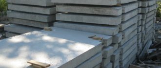
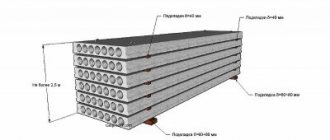
The most favorable option is to install the slabs immediately after delivery. If installation needs to be postponed, it is important to organize the storage of the slabs correctly. To do this, you will need a pre-prepared, flat surface. Laying the slabs on the ground is not allowed due to the uneven distribution of the load on the lower slab from the upper ones and the possibility of damage.
The slabs are stacked in batches of 8-10 pieces. A 200*200 mm beam is usually used as a spacer for the bottom row. The spacer for subsequent rows is an inch board with a thickness of 25 mm. The position of the gaskets should not be further than 45 cm from the ends of the slabs, maintaining verticality above each other. These rules will ensure that the load on the stack is evenly distributed.
So, by following all these rules for storing, laying out and installing floor slabs, you will ensure the reliability of the entire structure!
A ceiling is a structure that divides a building into floors. Depending on the location of the ceilings, they can be above the basement (between the basement and the first floor), between floors and attic (between the attic and the top floor of the building).
In addition to the fact that floors serve as fencing, they perceive and transmit various loads to the vertical structures of the building (weight of equipment, weight of people in the building, etc.), and also provide spatial rigidity of the building.
The roof is the upper enclosing structure of a building that protects it from precipitation and solar radiation.
The top waterproof layer is called the roof. To construct the roof, sheet metal, asbestos-cement tiles and sheets, rolled materials (roofing felt, roofing felt), etc. are used. The roof, together with the attic floor, forms the covering of the building.
According to the design of the roof, it can be attic, consisting of a roof and sheathing or a continuous flooring, which rests on the load-bearing part of the roof - rafters or trusses. Such roofs are usually made pitched. They have a significant slope, the magnitude of which depends on the roofing material and the design features of the building. Roofs are also without attics. The surface of such a roof usually has a slight slope. In this case, the roof and attic floor are combined into one structure, which is called a non-attic covering.
Roofless coverings are widely used in industrial and agricultural buildings. They are more economical than attic roofs, so they are also used in the construction of residential and public buildings.
Load-bearing structures of floors, coverings and roofs, as a rule, are assembled from industrially manufactured parts: beams, trusses, slabs and panels of floors and roofings, wooden panels of prefabricated rafters, etc., the installation of which is carried out according to the corresponding plans for floors, coverings and rafters. For example, installation of floors is carried out according to floor plans. Floor plans show:
The structural skeleton of the building (load-bearing walls, columns, purlins - main beams, etc. and the building axes passing through them);
Floor elements (beams, panels and slabs, floor panels);
Elements that provide rigidity to the floor structure (anchors, linings, metal embedded parts, etc.). If the floor is crossed by channels or openings, these are also shown on the plan.
In order to make the drawing more visual, all elements directly related to the floor structure are outlined with a line of thickness 6 = 0.4-^0.8 mm,
And the contours of the remaining elements, including walls and columns, are a line of thickness
L/2.
All prefabricated floor elements are marked in accordance with the current catalogs of industrial products or specifications provided for in this project.
Floors that are not made from factory-made parts (filled in place) are shaded on the floor plan. The dimensions on the floor plans are:
A) between the alignment axes of the walls;
B) between the axes of the beams with these dimensions tied to the axes of the walls;
C) individual elements of the floor structure (width of placement in place, etc.);
D) holes, channels, fire breaks (brick walls separating the heating elements of buildings from flammable parts).
Drawings of floor plans are usually supplemented with specifications of the wooden, metal and reinforced concrete elements included in the design of each floor, as well as notes indicating the design features of this floor and the work performed.
Floor slab plan
An important step in drawing up a diagram is calculating the number of slabs. The indicator is defined as the sum of the floor areas and the area of one slab. When dividing, the result may be a non-integer value; rounding is carried out upward.
When considering the plan, you can choose several types of floors for different floors. Differences are often made for rooms below grade level, but changes can be made for each floor separately.
It is better to leave the drawing of the floor plan in the hands of a professional. The work itself can be done by a beginner or an unskilled worker, but the drawing requires an understanding of the properties of reinforced concrete slabs and correct calculations. Any mistake can result in the destruction of the structure. The architect will take into account the building's features and help determine the best plan.
Floor slab layout plan
After drawing up sketches regarding the approximate location of the slabs, it is important to determine the axes and overall dimensions of the panels along the axes. The dimensions of the slab will help determine the height of the building and the number of panels. Vertical dimensional values take into account relative heights from the finished floor level.
To draw up a plan, it is important to take into account the location of the load-bearing walls to which the floors will be attached.
When laying out the load-bearing elements of the floor, you will see that the selection of their width is as important as the length
Plan of load-bearing floor structures
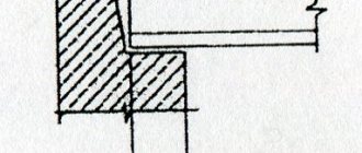
Hollow-core floors are supported on a load-bearing brick wall on the short side, at least 90 mm. If the support is cellular concrete - 120-150 mm. It is not recommended to rest the long side on self-supporting elements. For the construction of low-rise buildings, it is better to use slabs with a width of 1.8 m and a length of up to 7.2 m.
If the walls of the building are made of cellular concrete, it is better to use a ceiling made of the same material. On the short side they should be supported by load-bearing walls - 10-15 cm, and on the sides - 2-5 cm. To strengthen the structure, the plan should include a reinforced concrete belt made of a monolith that encircles the building and internal walls.
When drawing up a plan for a structure made of prefabricated reinforced concrete or cellular concrete slabs, it is important to make footnotes with the dimensions of the elements, indicate the sections of the monolith, the height of the support, the width of the reinforced concrete belt and the anchorage of the panels.
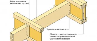
Mostly for floors, I-beams with a height of 16-27 cm are used. Floor beams should rest on the walls by 18 cm or more. To form a hard drive, you need to connect the beams together and attach them to the walls. The distance between the beams is 60, 77, 80 cm or 1, 1.1 m. The type of interbeam filler has the greatest influence on the step. It is better to fix the beams along the edges of the structure near the load-bearing walls (up to 5 cm from the edge of the beam to the wall). It is better to make elements of non-standard shape from monolithic concrete.
Upon completion of the arrangement of load-bearing elements on the walls of the building, they proceed to applying designations and dimensions
Installation process
As with all work, the first thing you need to do is purchase all kinds of materials and equipment. In particular, to make formwork, you will need either a collapsible structure, which can be rented from construction companies, or material for making this structure yourself.
If the installation will be done with your own hands, then for the formwork you need to prepare moisture-resistant plywood or boards. The plywood must be at least 2 centimeters thick, and the boards must be at least 2.5 centimeters thick.
When constructing a building, in some cases it may be necessary to install a special reinforcing element. It is called a monolithic belt for floor slabs. It is a reinforced concrete strip that runs along the perimeter of the building and serves as a support for the structure being constructed.
- The process of installing the slab begins with the installation of racks or supports that will support the slab during its installation and hardening. They are installed with a certain step - it is regulated by the distance between the floor beams and its size.
- Next, the longitudinal beams are installed. They need to be placed in special fastenings on previously installed supports. People call these mounts “crowns” or “forks.” When laying beams, you need to take into account that the surface of the formwork must be strictly horizontal. All beams are covered with plywood or boards. After forming the slab, these parts of the formwork will need to be removed, so it is necessary to take into account these nuances of their installation.
- When the beams are laid, you can begin assembling the horizontal part of the formwork, checking the horizontal plane. It must be observed absolutely throughout the entire area.
- When assembling, you should pay attention to how smooth the plane will be - this determines how smooth the ceiling, which is its lower part, will be. In order to obtain a surface of the highest quality, as well as to prevent concrete from leaking into the cracks, a waterproofing film is laid.
- Next, the vertical elements are installed. They need to be installed so that after pouring, the edges of the slab overlap the walls with sufficient margin. The required distance is indicated in SNiP.
- After this, they begin to reinforce the entire surface of the future slab. Two rows of mesh made from reinforcing bars are laid. The cell of the resulting grid should be about 20 centimeters. The first layer is laid at a distance of about 2.5 centimeters from the bottom plane of the formwork. In order to raise the mesh, special plastic spacers are used.
- The second layer of mesh is mounted at the same distance from the upper plane of the future slab. To secure two layers of mesh at the required distance, special stands are bent from reinforcing bars. All layers of the mesh and all its elements are connected to each other with knitting wire.
- When the reinforcement is laid and all the formwork elements are in place, the process of pouring the mortar begins. The grade of concrete is chosen for a reason, but based on data on the expected load on the slab. Do not forget that all technological holes in the resulting slab must be fenced in advance with specially made boxes.
- After pouring the solution, it must be compacted with a special vibrating machine for concrete. This will make the poured ceiling more uniform in structure, and will also expel all air bubbles formed during pouring.
- The resulting surface is moistened within a week from the moment the solution is poured. After this, constant moisturizing is not required. But you still need to control the drying of the surface.
- It may take up to 30 days for the concrete to completely harden. It all depends on the chosen brand of concrete and the thickness of the structure being created.
After the specified period, the formwork is completely removed, and the ceiling is ready for use.
General installation information
Prefabricated reinforced concrete slabs are installed with a minimum gap between each other. Installation will require special lifting equipment. The seams of the floors are filled with cement mortar. Metal anchors that are mounted to the hinges of the slabs will help create a complete and extremely rigid horizontal floor. In places where the panels come into contact with the internal slabs, composite anchors are used, which are fastened by welding.
If precast slabs are based on external walls, it is recommended to attach their end parts to the masonry using L-shaped anchors. After installation, they are filled with cement, it will prevent corrosion. If gaps appear between the slabs and partitions, they can be eliminated with brickwork.
An important rule is that reinforced concrete slabs are laid exclusively on load-bearing walls; other self-supporting structures and partitions are laid after the slabs are installed.
When laying slabs, a foundation is formed under load-bearing and self-supporting walls with a thickness of over 250 mm. Additionally, the base is installed under ventilation ducts and individual supporting elements. To create a foundation sketch, you should take into account the size of the base under the walls and determine the connection of the base of the foundation to the modular alignment layers. When using columnar and prefabricated foundations, the width of the foundation slabs is determined according to the strength required to withstand the loads.
In addition to the good economic effect in terms of construction costs and speed of building construction, the use of reinforced concrete provides a number of other advantages
The thickness of the rubble concrete and rubble strips is determined 8-10 cm wider than the wall. The size of the prefabricated foundation is determined equal to the thickness of the blocks (30-60 cm), but the wall itself is sometimes 4-5 cm wider than the base. Common block lengths: 80, 120, 240 cm To reduce pressure on the soil, the foundation can be made with an expanded base with 1-2 ledges, dimensions (HxW) - 30-40x15-25 cm. In a prefabricated foundation for widening, a foundation slab-cushion with reinforcement with a width of 60 cm to 1.6 m is used , height 30 cm.
Construction portal No. 1
04/04/2019 admin Comments No comments
To reduce material consumption, floor slabs are designed to be lightweight - hollow or ribbed (Fig. 7.2a). When removing concrete from the tension zone, only the ribs with the width necessary to accommodate the welded frames and ensure the strength of the panels along the inclined section are retained. In this case, the slab in the span between the crossbars bends like a T-section beam. The top flange of the slab also acts on local bending between the ribs. The lower shelf, forming a closed void, is created if it is necessary to install a smooth ceiling.
Rice. 7.2. Cross-sectional shapes of floor slabs
The slabs are made with voids of various shapes: oval, round, etc. In panels of considerable width, several adjacent voids are arranged (Fig. 7.2.a).
The general principle of designing floor slabs of any cross-sectional shape is to remove as much concrete as possible from the tension zone while maintaining the vertical ribs that ensure the strength of the element along the inclined section, in conjunction with the technological capabilities of the manufacturer.
According to the cross-sectional shape, slabs can have oval, round and vertical voids, ribbed with ribs up (with a clean floor along the ribs), ribbed with ribs down, solid (Fig. 7.2a - f).
In slabs with voids, the minimum thickness of shelves is 25-30 mm, ribs 30-35 mm; in ribbed slabs with ribs downwards, the thickness of the shelf (slab) is 50-60 mm.
For a given length of slabs of different types, their width is taken such as to obtain weight gradations that do not exceed the lifting capacity of assembly cranes 3...5 tons, and sometimes more. Slabs 3.2 m wide with a span of 6 m cover the entire living room; the mass of such slabs with voids is 5...6 tons. Hollow and solid slabs, which make it possible to create a smooth ceiling, are used for residential and civil buildings, ribbed panels with the ribs down are used for industrial buildings with standard loads over 5 kN/m 2.
The efficiency of the slab is assessed by the reduced thickness of concrete, which is obtained by dividing the volume of concrete of the panel by its area and by the consumption of steel reinforcement (Table 7.1).
Technical and economic indicators of floor slabs with a nominal span of 6 m and a standard load of 6-7 kN/m 2
The most economical in terms of concrete consumption are slabs with oval voids; the reduced concrete thickness in them is 9.2 cm, while in slabs with round voids the reduced concrete thickness reaches 12 cm. However, when producing panels with oval voids in factories, technological difficulties arise due to the fact that after removing the void formers (punches) the walls channels of a freshly molded product sometimes collapse.
Design span of slabs l
taken equal to the distance between the axes of its supports (Fig. 7.3. a - c);
when supported on the top of the crossbars l
=
l
-
b/2
(where
b
is the width of the crossbar);
when leaning on the shelves of the crossbars l
=
l
–
a
–
b (a
is the size of the shelf). When supported with one end on the crossbar and the other on the wall, the design span is equal to the distance from the axis of the support on the wall to the axis of the support on the crossbar.
Rice. 7.3. Design spans and sections of slabs
Slab section height h
must be selected so that, along with the strength conditions, the requirements of rigidity (maximum deflections) are satisfied. For spans of 5–7 m, the height of the slab section is determined mainly by rigidity requirements. The preliminary height of the panel section, which simultaneously satisfies the strength conditions and rigidity requirements, can be determined using the approximate formula
(7.1)
where with
- coefficient, for hollow panels it is 18 - 20, for ribbed panels with a shelf in a compressed zone - 30 - 34;
- long-term standard load per 1 m 2 of floor;
- short-term standard load per 1 m 2 of floor;
— coefficient of increase in deflections under long-term load: for hollow panels = 2, for ribbed panels with a shelf in the compressed zone = 1.5.
The cross-sectional height of prestressed slabs can be pre-set equal to:
h= l
/20 - for ribbed ones;
h= l
/30 - for hollow ones.
When calculating the bending moment strength, the width of the rib is equal to the total width of all the ribs of the slab, and the calculated width of the compressed flange is taken to be equal to the total width of the panel. With a small thickness of the compressed flange, when ,
The width of the shelf entered into the calculation should not exceed
(7.2)
where n
- the number of ribs in the cross section of the panel.
In a ribbed panel with the ribs downwards, with the thickness of the flange but in the presence of transverse ribs, the width of the flange entered into the calculation is taken to be equal to the full width of the panel.
Thus, the calculation of the strength of the slabs is reduced to the calculation of a T-section with a flange in the compressed zone.
When calculating deflections, sections of panels with voids are reduced to equivalent I-sections. For panels with round voids, the equivalent I-section is found from the condition that the area of a round hole with a diameter d
equal to the area of a square hole with a side (Fig. 7.4):
(7.3)
Rice. 7.4. Equivalent sections of slabs for calculating deflections
Section of panels with oval voids (see Fig. 7.4)
lead to an equivalent I-section, replacing the oval cross-section of the void with a rectangular one with the same area and the same moment of inertia and observing the condition that the center of gravity of the oval and the replacing rectangle coincide.
Designating b1
and
h1
- the width and height of the equivalent rectangle;
F
and
I
- area and moment of inertia of the oval:
; (7.4)
The panel flange operates under local bending as a slab partially clamped on supports with span l
, equal to the clear distance between the ribs. In ribbed panels with ribs downwards, pinching of the flange is created by pouring concrete into the seams, which prevents the ribs from rotating (Fig. 7.5, a). Bending moment
(7.5)
In a ribbed panel with transverse intermediate ribs, the bending moments of the flange can be determined as in a slab supported along the contour and working in two directions (Fig. 7.5, b).
Rice. 7.5. Calculation diagrams of slab flanges
Welded mesh and frames made of ordinary reinforcing wire and hot-rolled reinforcement of a periodic profile are used (Fig. 7.6). As prestressed longitudinal reinforcement, rods of classes S800, S1200, high-strength wire and ropes are used. Reinforcement can be done without prestressing if the panel span is less than 6 m.
Longitudinal working reinforcement is located across the entire width of the lower flange of the section of hollow-core panels and in the ribs of ribbed panels.
Transverse rods are combined with longitudinal mounting or working non-prestressing reinforcement into flat welded frames, which are placed in the ribs of the slabs. Flat welded frames in round-hollow slabs can only be placed in the support areas, through one or two ribs. Anchors from corners or plates are welded to the ends of the longitudinal non-tensioned reinforcement of ribbed slabs to secure the rods to the support.
Solid slabs of heavy and lightweight concrete are reinforced with longitudinal prestressing reinforcement and welded mesh. Mounting loops are placed at the four corners of the slabs. In places where hinges are installed, solid panels are reinforced with additional upper meshes.
An example of reinforcement of a ribbed floor panel of an industrial building is shown in Fig. 7.7. The nominal width of this panel is considered to be 1.5 m. Such slabs are also used with a width of 3 m.
Rice. 7.7. Reinforcement of a ribbed floor slab
Assembly connections of all types of panels are made by welding steel embedded parts and filling the joints between the slabs with concrete. In the longitudinal side edges of the slabs, depressions are provided, designed to form intermittent keys, ensuring the joint operation of the slabs for shear in the vertical and horizontal directions (Fig. 7.8a). With such connections of prefabricated floor elements, the floors are rigid horizontal diaphragms.
If the temporary loads on the floors are more than 10 N/m2, then it is advisable to convert the ribbed slabs into continuous ones when cementing the seams. For this purpose, the seams between the ribbed slabs on the supports are reinforced with welded saddle-shaped frames crossing the crossbar (Fig. 7.8b). For loads acting after embedding, such slabs are designed as continuous.
Sequence of installation of floor slabs
Initially, you need to complete 2 steps:
- Preparation. It is important to create the correct level between all the supporting walls of the structure. The permissible difference is 1 cm, it is not necessary to eliminate it. To check the horizontal plane, use a building level. A beam is laid between opposite walls and the evenness is checked. If there are small irregularities, they can be eliminated with cement mortar.
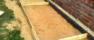
- Next, a distribution belt is made to level the wall. The reinforcing belt is made of cement M500 1 to 3 with sand. It is important to ensure the cleanliness of the sand, rinse and sift if necessary. A solution of medium viscosity is prepared. The mixture is poured into the formwork and pierced or tamped to remove voids. The solution takes up to 3-4 weeks to dry.
The main qualities for which reinforced concrete is valued are always called strength and good resistance to bending moment.
Floor slab installation technology
To install prefabricated reinforced concrete slabs, it will be necessary to rent a crane and 4 workers: a driver, a slinger and 2 installers.
Load-bearing walls should be calculated taking into account the need for a 5 cm gap on the street side. Insulation is placed in the recess; it prevents drafts through the cracks in the ceiling. Wear of thermal insulation in such houses leads to cold, dampness and drafts.
Installation procedure:
- Concrete is laid in a layer of 15-20 mm on the prepared cement mortar cushion on the supporting walls.
- The panel is lifted with a crane and placed on top of the installation site.
- Installers rotate the slab to guide it to the desired position. Crowbars will help to accurately position the slab before removing the slings. The correct location implies a contact point between the wall and the slab of at least 15 cm on each side.
- The slings are released and a final check of the installation is made.
Normals
the Normal panel (Fig. 15) are designed to call standard reference dialog boxes and quickly perform auxiliary calculations when designing reinforcement (according to SNiP 2.03.01-84*, etc.). All values determined by these tools, presented in the table below, are used to construct and verify detailed and schematic reinforcement objects. Most of the tools can be quickly accessed from dynamic panels and dialog boxes of detailed and schematic reinforcement tools. The obtained data is regulated by regulatory documents. In addition, some regulatory requirements are automatically controlled when constructing detailed reinforcement objects.
Normal panel tools
Checking the correct installation of floor slabs on supporting load-bearing walls
A viewfinder and a building level will help you most accurately determine the correct installation. If the walls have a difference of more than 4 mm on opposite sides, the slab should be re-installed. It is raised, the solution is corrected and the mixture is added in large quantities from the low side. If the cement begins to harden, it is better to remove it and mix it again. Even after adding water to the old mixture, it will no longer acquire the desired strength. If there are no problems with the level, the slabs are fastened.
To fix reinforced concrete panels, anchors are welded to the mounting loops. Next, the loops are welded together. The cracks are filled with cement. To prevent the solution from spilling out from below, crushed stone (up to 2 cm) is poured into the gap.
The following tools will be useful during the fastening process:
- tap;
- compressor unit;
- scaffolding;
- building levels;
- hammers, including jackhammers;
- crowbars;
- trowels;
- hacksaws for metal;
- tank or surface for preparing the solution.
Features of installing prefabricated floor slabs in private construction
The procedure is similar to the previous methods, but there are differences that occur due to the reduction in size and weight of the slabs. Even with a reduction in weight, the load on the supporting elements remains high. To prevent the destruction of the structure, you will have to increase the estimate to order the calculation of the load, the construction of the foundation, and the thickening of the walls. An additional cost is the need to hire skilled workers with experience.
It is easier to perform the ceiling from a wooden beam; the technique is much easier and less expensive. Reinforced concrete slabs are clearly preferred when constructing flat roofs. Roll or sheet roofing material is simply laid on top of the panels. When using reinforced concrete slabs for roofing, a more durable and durable coating is obtained.
Flooring with wooden beams is a load-bearing structure that separates adjacent rooms: floors, attic, underground. When constructing it, factors such as load-bearing capacity, sound and heat insulation, seismic resistance and heat resistance are taken into account. This structure regularly experiences loads and atmospheric influences, so it must meet the criteria of strength and wear resistance. According to their purpose, floors are classified into basement, interfloor and attic.
Installation of interfloor floors using wooden beams
The covering of the second floor using wooden beams is carried out using the same technology as the installation of basement structures. The main difference between the interfloor flooring and the floor flooring is the presence of a double subfloor. In this case, the lower subfloor is the ceiling of the 1st floor and is made of boards with a smaller cross-section.
The construction of attic and interfloor ceilings is carried out using the following technology:
- Load-bearing beams are installed in the landing slots.
- A windproof film is attached to the bottom using a construction stapler.
- The subfloor is attached below.
- Insulation is lined in the niches between the beams. This can be mineral wool, polystyrene foam, or ecowool based on split paper.
- Boards are laid on top of the insulation and the upper subfloor is screeded.
Ways to strengthen wooden floor beams
Conventionally, beam strengthening technologies can be divided into several types:
Restoration . This category includes methods such as reinforcement with wooden overlays, metal plates, carbon fiber wrapping, and prosthetics. Let's consider each of the options in more detail.
Damaged beams (rotten, cracked, potentially weak) can be strengthened with wood overlays. To do this, the beam itself is cleaned with sandpaper or a plane and treated with an antifungal agent. A beam with a smaller cross-section is laid on both sides. The structure is tightened with cords and stitched with through bolts.
The load-bearing capacity of broken logs is restored using metal prostheses using the technology described above. The hardware is applied to the cleaned and processed beam and tightened onto a series of through bolts.
Carbon fiber glued to damaged timber.
The technology for restoring floors using carbon fiber is simple and easy. To do this, the damaged area is glued with several layers of carbon material.
Prosthetics using metal prostheses and onlays.
Prosthetics are used to increase the strength and wear resistance of the joints between the timber and the wall. This is where the effects of corrosion and wear most often occur due to the maximum pressure. Preventive measures are taken at the stage of initial installation of the structure. Metal plates are sewn with bolts to the tenon of the timber. The reinforced structure is installed in the socket. An analogue of onlays is a metal prosthesis. It is drilled into the body of the beam and installed in a small hole in the wall.
The reconstruction category includes methods such as:
- installation of supports (columns, vertical beams);
- installation of additional beams.
If the load-bearing capacity of the timber is insufficient, it is often reinforced with vertical supports. Installation of the pile allows you to redistribute the pressure from the beam to the support. This technology is most popular for renovation work in attics and under the floor.
With a meter step, you can increase the load-bearing capacity of wooden floor beams using additional beams. To do this, the ceiling is completely dismantled and timber is installed in increments of 50 cm.
Formwork
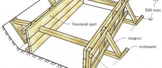
To form a semi-liquid concrete mixture into the future floor, it is necessary to make formwork. Only construction organizations can afford to buy inventory formwork for ceilings. For a private developer, these expenses are completely unacceptable, so the formwork was made with their own hands for the ceiling.
To reduce the cost of flooring, the formwork can be made removable by pouring individual areas of the floor, and after the concrete has hardened, it can be moved to a new area. But this process is very long, since it is recommended to remove the formwork after about a week, when the concrete has gained 50% strength.
Permanent formwork made of profiled steel sheets, laid on purlins made of metal or wooden beams, will help speed up the process. But, with a large area, a lot of sheets will be required, and their cost will have to be included in the cost of the ceiling, since it will be almost impossible to remove them.
For a house under construction, it was decided how to make formwork inexpensive, and at the same time, not delay the process of installing the floor:
- for the formwork runs, installed in increments of 500-600 mm, a 200 x 50 mm edged board was used, which was later used to construct gable roof rafters;
- the racks for the purlins were made of a 100 x 50 mm bar, which I later used to install lathing under the metal tile roof;
- the flooring was made of boards 150 x 25 mm, which were securely covered with dense polyethylene sheets left over from the packaging of aerated concrete blocks; subsequently, the boards were used to construct the upper floor in some attic rooms.
Since it was necessary to cover a span of 9,400 mm, even at the design stage it was decided to pour a reinforced concrete beam lying on two columns in the middle of the span simultaneously with the ceiling. The permanent formwork for the beam was two channels 200 mm high, which added strength to it. The result was two spans of 4,600 mm, separate floor formwork, with common reinforcement.
The racks and purlins must be fastened with metal connecting plates on self-tapping screws. If you use nails, removing the formwork will be very difficult. The flooring, on the contrary, is sewn on with 60 mm nails, since they will ensure the necessary movements of the boards during pouring if the latter are not tightly pressed to the purlins.
After installing the flooring, vertical formwork parts are installed, consisting of ready-made panels, the width of which is approximately 100 mm greater than the thickness of the ceiling. They can simply be screwed to the walls with self-tapping screws. These elements should keep the concrete mixture from spreading. Sheets of extruded polystyrene foam are subsequently installed along the vertical panels. They will serve as insulation for the ends of the floor.
The duration of this stage turned out to be short, since I used the panels that were used when constructing the strip foundation and the ceiling of the first floor.
Future openings for ventilation duct shafts, as well as for the flight of stairs, must be carefully marked and limited by vertical formwork elements made from 100 x 50 mm bars.
Formwork for monolithic reinforced concrete floors
I covered the flooring with polyethylene, which I attached to the boards using a construction stapler. I taped the joints with office adhesive tape. You need to cover the boards carefully for two reasons:
- to prevent water loss and changes in the water-cement ratio of the concrete mixture;
- in order to keep the flooring boards clean and suitable for further use.
The surface of the formwork for a monolithic ceiling must be carefully insulated.
I fenced the ventilation ducts made in the load-bearing wall with boxes made of boards and bars. All cracks and leaks were filled with polyurethane foam.
The installation of the formwork took five full days, and I did almost all the work myself. Sometimes I needed the help of my eldest son.
