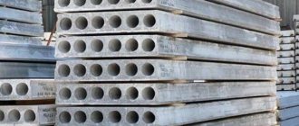
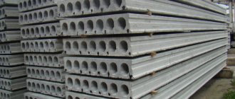
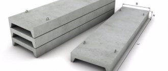
Slabs of superstructures
The Beton-S company manufactures and sells slabs for spans, which can be purchased on favorable terms with a guarantee of high quality for each product. All products undergo strict production control to ensure compliance with GOST requirements. High-strength concrete is used to produce span slabs. Reinforcement with steel elements gives the structure additional rigidity, strength and stability during operation under conditions of increased loads.
The span slabs that our company offers to buy are reinforced concrete elements used in bridge construction. Thanks to the use of such products, it is possible to reduce construction costs by saving on the use of expensive metal products, as well as increase the overall strength and reliability of the structure. The main purpose of the span slabs is to bridge the spans between the bridge supports. The need for high strength of such products is due to the requirement to withstand significant loads from the road surface, moving loads from vehicles moving across the bridge and their own weight. Slabs of span structures, which can be purchased from our company, are able to withstand all declared loads, withstand sudden temperature fluctuations and numerous freezing cycles, as well as seismic impacts. You can order span slabs of the required size by contacting the manager of our company. The specialist will calculate the exact cost of the products and tell you about the terms of delivery.
| Product name | Overall dimensions, mm | volume, m3 | Weight, t | ||
| Length | Width | Height | |||
| 5970 | 1490 | 300 | 0,565 | 1,41 | |
| PKZH – 2 | 5970 | 1490 | 300 | 0,565 | 1,41 |
| 5970 | 1490 | 300 | 0,565 | 1,41 | |
| PKZH – 4 | 5970 | 1490 | 300 | 0,565 | 1,41 |
| PKZH – 5 | 5970 | 1490 | 300 | 0,565 | 1,41 |
| 5550 | 1485 | 400 | 0,89 | 2,225 | |
| IP1-2 | 5550 | 1485 | 400 | 0,89 | 2,225 |
| IP1-3 | 5550 | 1485 | 400 | 0,89 | 2,225 |
| IP1-4 | 5550 | 1485 | 400 | 0,89 | 2,225 |
| 5550 | 1485 | 400 | 0,89 | 2,225 | |
| IP1-6 | 5550 | 1485 | 400 | 0,89 | 2,225 |
| IP2-1 | 5050 | 1485 | 400 | 0,81 | 2,025 |
| IP2-2 | 5050 | 1485 | 400 | 0,81 | 2,025 |
| IP2-3 | 5050 | 1485 | 400 | 0,81 | 2,025 |
| IP2-4 | 5050 | 1485 | 400 | 0,81 | 2,025 |
| IP2-5 | 5050 | 1485 | 400 | 0,81 | 2,025 |
| IP3-1 | 5550 | 740 | 400 | 0,6 | 1,5 |
| IP3-2 | 5550 | 740 | 400 | 0,6 | 1,5 |
| IP3-3 | 5550 | 740 | 400 | 0,6 | 1,5 |
| IP3-4 | 5550 | 740 | 400 | 0,6 | 1,5 |
| IP3-5 | 5550 | 740 | 400 | 0,6 | 1,5 |
| IP4-1 | 5050 | 740 | 400 | 0,55 | 1,375 |
| IP4-2 | 5050 | 740 | 400 | 0,55 | 1,375 |
| IP4-3 | 5050 | 740 | 400 | 0,55 | 1,375 |
| IP4-4 | 5050 | 740 | 400 | 0,55 | 1,375 |
| IP4-5 | 5050 | 740 | 400 | 0,55 | 1,375 |
| 5970 | 1490 | 300 | 0,6 | 1,5 | |
| 2PG6-3AtVt | 5970 | 1490 | 300 | 0,6 | 1,5 |
| 2PG6-4AtVt | 5970 | 1490 | 300 | 0,6 | 1,5 |
| 2PG6-2AIIIvt | 5970 | 1490 | 300 | 0,6 | 1,5 |
| 2PG6-3AIIIvt | 5970 | 1490 | 300 | 0,6 | 1,5 |
| 2PV6-4AtV-4 | 5970 | 1490 | 300 | 0,6 | 1,5 |
| 2PV6-4AtV-7 | 5970 | 1490 | 300 | 0,6 | 1,5 |
| 2PV6-4AtV-10 | 5970 | 1490 | 300 | 0,6 | 1,5 |
| 2PV6 3 AtV-4 | 5970 | 1490 | 300 | 0,78 | 1,925 |
| 5970 | 1490 | 300 | 0,78 | 1,925 | |
| P2 2AIIIv | 5650 | 1485 | 300 | 0,76 | 1,9 |
| P2 3АIIIв | 5650 | 1485 | 300 | 0,76 | 1,9 |
| P2 4AIIIv | 5650 | 1485 | 300 | 0,76 | 1,9 |
| P2 5AIIIv | 5650 | 1485 | 300 | 0,76 | 1,9 |
| P2 6AIIIv | 5650 | 1485 | 300 | 0,76 | 1,9 |
| P2 7AIIIv | 5650 | 1485 | 300 | 0,76 | 1,9 |
| P2 8AIIIv | 5650 | 1485 | 300 | 0,76 | 1,9 |
| P2 2AtV | 5650 | 1485 | 300 | 0,76 | 1,9 |
| 1P3 2AtVt | 5550 | 1485 | 400 | 0,9 | 2,25 |
| 1P3 3AtVt | 5550 | 1485 | 400 | 0,9 | 2,25 |
| 1P3 4AtVt | 5550 | 1485 | 400 | 0,9 | 2,25 |
| 1P3 2AIIIv | 5550 | 1485 | 400 | 0,9 | 2,25 |
| 1П3 3АIIIв | 5550 | 1485 | 400 | 0,9 | 2,25 |
| 1П3 4АIIIв | 5550 | 1485 | 400 | 0,9 | 2,25 |
| 1P3 5AIIIv | 5550 | 1485 | 400 | 0,9 | 2,25 |
| 1P3 6AIIIv | 5550 | 1485 | 400 | 0,9 | 2,25 |
| 1P4 3AtVt | 5050 | 1485 | 400 | 0,83 | 2,1 |
| 1P4 4AtVt | 5050 | 1485 | 400 | 0,83 | 2,1 |
| 1P4 5AtVt | 5050 | 1485 | 400 | 0,83 | 2,1 |
| 1P4 2AIIIvt | 5050 | 1485 | 400 | 0,83 | 2,1 |
| 1P4 3AIIIvt | 5050 | 1485 | 400 | 0,83 | 2,1 |
| 1P4 4AIIIvt | 5050 | 1485 | 400 | 0,83 | 2,1 |
| 1P4 5AIIIvt | 5050 | 1485 | 400 | 0,83 | 2,1 |
| 1P4 6AIIIvt | 5050 | 1485 | 400 | 0,83 | 2,1 |
| 1P7 1AIII | 5550 | 740 | 400 | 0,6 | 1,5 |
| 1P7 2AIII | 5550 | 740 | 400 | 0,6 | 1,5 |
| 1P7 3AIII | 5550 | 740 | 400 | 0,6 | 1,5 |
| 1P7 4AIII | 5550 | 740 | 400 | 0,6 | 1,5 |
| 1P7 5AIII | 5550 | 740 | 400 | 0,6 | 1,5 |
| 1P7 6AIII | 5550 | 740 | 400 | 0,6 | 1,5 |
| 1P8 1AIII | 5050 | 740 | 400 | 0,55 | 1,4 |
| 1P8 2AIII | 5050 | 740 | 400 | 0,55 | 1,4 |
| 1P8 3AIII | 5050 | 740 | 400 | 0,55 | 1,4 |
| 1P8 4AIII | 5050 | 740 | 400 | 0,55 | 1,4 |
| 1P8 5AIII | 5050 | 740 | 400 | 0,55 | 1,4 |
| 1P8 6AIII | 5050 | 740 | 400 | 0,55 | 1,4 |
| 1P3 2AtVt-2 | 5550 | 1485 | 400 | 0,97 | 2,4 |
| 1P3 2AtVt-3 | 5550 | 1485 | 400 | 0,93 | 2,3 |
| 1P3 3AtVt-2 | 5550 | 1485 | 400 | 0,97 | 2,4 |
| 1P3 3AtVt-3 | 5550 | 1485 | 400 | 0,93 | 2,3 |
| 1P3 4AtVt-3 | 5550 | 1485 | 400 | 0,97 | 2,4 |
| 1P3 5AtVt-3 | 5550 | 1485 | 400 | 0,93 | 2,3 |
| 1P3 2AIIIv-2 | 5550 | 1485 | 400 | 0,97 | 2,4 |
| 1P3 2AtVt | 5550 | 1485 | 400 | 0,93 | 2,3 |
| 2P1 2AIIIvt-1 | 5950 | 1485 | 400 | 0,95 | 2,4 |
| 2P1 2AIIIvt-2 | 5950 | 1485 | 400 | 0,9 | 2,25 |
| 2P1 2AIIIvt-3 | 5950 | 1485 | 400 | 0,89 | 2,23 |
| 2P1 3AIIIvt-1 | 5950 | 1485 | 400 | 0,95 | 2,4 |
| 2P1 3AIIIvt-2 | 5950 | 1485 | 400 | 0,9 | 2,25 |
| 2P1 3AIIIvt-3 | 5950 | 1485 | 400 | 0,89 | 2,23 |
| PRS 26.15-4АIII | 2650 | 1490 | 220 | 0,61 | 1,52 |
| PRS 26.15-11AIII | 2650 | 1490 | 220 | 0,61 | 1,52 |
| PRS 26.15-17AIII | 2650 | 1490 | 220 | 0,61 | 1,52 |
| PRS 56.15-7AIII | 5650 | 1490 | 220 | 1,13 | 2,89 |
| PRS 56.15-11AIII | 5650 | 1490 | 220 | 1,13 | 2,89 |
| PRS 56.15-15AIII | 5650 | 1490 | 220 | 1,13 | 2,89 |
| PRS 68.15-9AIII | 6850 | 1490 | 220 | 1,45 | 2,89 |
| PRS 68.15-11AIII | 6850 | 1490 | 220 | 1,45 | 2,89 |
| PRS 68.15-8AIII | 6850 | 1490 | 220 | 1,45 | 2,89 |
| 4PG6 3AtVt | 5970 | 1490 | 300 | 0,615 | 1,538 |
| 4PG6 2AIIIvt | 5970 | 1490 | 300 | 0,615 | 1,538 |
| 4PG6 3AIIIvt | 5970 | 1490 | 300 | 0,615 | 1,538 |
| 4PV6 3 AtV-4 | 5970 | 1490 | 300 | 0,78 | 1,925 |
| 4PV6 2AIIIvt-4 | 5970 | 1490 | 300 | 0,78 | 1,925 |
| 4PV6 3AIIIvt-4 | 5970 | 1490 | 300 | 0,78 | 1,925 |
| PG 3AtVt | 5970 | 2980 n | 300 | 1,07 | 2,7 |
| PG 3 3AIIIvt | 5970 | 2980 | 300 | 1,07 | 2,7 |
| 3PG6 2AIIIvt | 5970 | 2980 | 300 | 1,07 | 2,7 |
| 3PG6 3AIIIvt | 5970 | 2980 | 300 | 1,07 | 2,7 |
| 3PG6 4AIIIvt | 5970 | 2980 | 300 | 1,07 | 2,7 |
| 3PG6 5AIIIvt | 5970 | 2980 | 300 | 1,07 | 2,7 |
| PV4 3AtVt | 5970 | 2980 | 300 | 1,31 | 3,3 |
| PV4 4AIIIvt | 5970 | 2980 | 300 | 1,31 | 3,3 |
| PV4 5AIIIvt | 5970 | 2980 | 300 | 1,31 | 3,3 |
| PV4 6AIIIvt | 5970 | 2980 | 300 | 1,31 | 3,3 |
| PV4 7AIIIvt | 5970 | 2980 | 300 | 1,31 | 3,3 |
| PV7 3AtVt | 5970 | 2980 | 300 | 1,28 | 3,2 |
| PV7 4AIIIvt | 5970 | 2980 | 300 | 1,28 | 3,2 |
| PV7 4AtVt | 5970 | 2980 | 300 | 1,28 | 3,2 |
| PV7 5AIIIvt | 5970 | 2980 | 300 | 1,28 | 3,2 |
| PV7 5AtVt | 5970 | 2980 | 300 | 1,28 | 3,2 |
| PV10 3AtVt | 5970 | 2980 | 300 | 1,45 | 3,6 |
| PV10 3AIIIvt | 5970 | 2980 | 300 | 1,45 | 3,6 |
| PV14 3AtVt | 5970 | 2980 | 300 | 1,37 | 3,4 |
| PV14 4AtVt | 5970 | 2980 | 300 | 1,37 | 3,4 |
| PV14 3AIIIvt | 5970 | 2980 | 300 | 1,37 | 3,4 |
| PL 3AtVt | 5970 | 2980 | 300 | 1,07 | 2,7 |
| PL 3AIIIvt | 5970 | 2980 | 300 | 1,07 | 2,7 |
| PL 4AtVt | 5970 | 2980 | 300 | 1,07 | 2,7 |
| PL 4AIIIvt | 5970 | 2980 | 300 | 1,07 | 2,7 |
| 2PG12 3K7t | 11960 | 2980 | 455 | 2,96 | 7,4 |
| 2PG12 4K7t | 11960 | 2980 | 455 | 2,96 | 7,4 |
| 2PV12 3K7t | 11960 | 2980 | 455 | 3,2 | 8 |
| 2PV12 3K7t-10 | 11960 | 2980 | 455 | 3,31 | 8,3 |
| 2PV12 4K7t-10 | 11960 | 2980 | 455 | 3,31 | 8,1 |
| 2PV12 4K7t-14 | 11960 | 2980 | 455 | 3,22 | 7,9 |
| PRK 30.06 | 2980 | 630 | 100 | 0,13 | 0,33 |
Types and features according to the method of support
Construction norms SNiP regulate the possibility of supporting floor slabs on walls on 2, 3 and 4 sides. But here everything depends on the type of reinforced concrete products and the design features of the reinforcing frame. Thus, reinforced concrete products of the PB brands can only be supported on 2 sides, while PCs are produced in several types depending on the number of supporting sides.
On both sides
The support for such products is provided by 2 opposing wall structures. Laying is carried out on the narrow sides, since the reinforcement is made in the longitudinal direction.
Figure 6. Supporting reinforced concrete on 2 sides
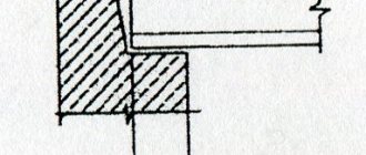
On three sides
These slabs are designed to cover U-shaped spans in the corners of buildings. The possibility of installation on 3 sides is ensured thanks to reinforced end reinforcement.
Figure 7. Laying the product with support on 3 sides
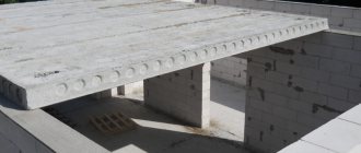
On four sides
Precast concrete products of these types are usually used in complex structures where optimal distribution of increased loads is required, and in the construction of additional superstructures. Due to the presence of a reinforcing frame at all ends, hollow-core floor slabs can be supported on 4 walls.
Design features of floor slabs
Structurally, the products are a solid rectangular slab with two longitudinal elements along the long sides, which play the role of beams that take the bending load. In larger slabs, transverse stiffeners are installed to give additional strength to the product.
The peculiarity of this product is that most of the concrete is removed from the tension zone and concentrated in the compression zone. In this way, a reduction in the weight and thickness of the entire element is achieved while maintaining the desired strength characteristics. Reducing the amount of concrete for production makes it possible to reduce their cost and, accordingly, the price for the end consumer.
Types and features according to the method of support
Construction norms SNiP regulate the possibility of supporting floor slabs on walls on 2, 3 and 4 sides. But here everything depends on the type of reinforced concrete products and the design features of the reinforcing frame. Thus, reinforced concrete products of the PB brands can only be supported on 2 sides, while PCs are produced in several types depending on the number of supporting sides.
On both sides
The support for such products is provided by 2 opposing wall structures. Laying is carried out on the narrow sides, since the reinforcement is made in the longitudinal direction.
Figure 6. Supporting reinforced concrete on 2 sides
On three sides
These slabs are designed to cover U-shaped spans in the corners of buildings. The possibility of installation on 3 sides is ensured thanks to reinforced end reinforcement.
Figure 7. Laying the product with support on 3 sides
On four sides
Precast concrete products of these types are usually used in complex structures where optimal distribution of increased loads is required, and in the construction of additional superstructures. Due to the presence of a reinforcing frame at all ends, hollow-core floor slabs can be supported on 4 walls.
Types of slabs
According to GOST 28042-89, there are several main sizes of slabs. The minimum length of the product ranges from 300x5970 mm, however, there are slab options with a width of up to 3 meters and a length of up to 18 meters.
In addition, they differ from each other in design:
- Products with a flat top plate. They, in turn, are divided into slabs without holes (marked PG), slabs with holes for ventilation (PV), slabs with holes for lighting equipment (PF, PS) and slabs with openings for a drop-off roof (PL);
- Shell slabs. They differ in that they have a vaulted surface. They are divided into the same subspecies as the previous version.
The classification also provides for the classification of slabs depending on their location: P1 - in rows, P2 - in rows and between columns, P3 - between columns and along the walls.
Control methods
6.1. Load tests of slabs to control their strength, rigidity and crack resistance (if this is provided for in the working drawings of the slabs) are carried out in accordance with GOST 8829 and the working drawings of these slabs.
When testing by loading, the slabs must withstand the control loads established by the working drawings of these slabs.
6.2. Test methods for concrete and concrete mixtures, as well as materials for their preparation, should be adopted for:
— heavy concrete — according to GOST 26633;
— lightweight concrete — according to GOST 25820;
— dense silicate concrete — according to GOST 25214.
6.3. Inspection of welded joints of reinforcement and embedded products - in accordance with GOST 10922.
6.4. Measurement of stresses in prestressed reinforcement, controlled after the end of its tension on the stops, according to GOST 22362.
6.5. Dimensions of the slabs, deviations from the straightness of the profile of their upper surface and the profile of the side faces, deviations from the flatness of the front lower (ceiling) surface, the difference in the diagonals of the slab, the dimensions and position of reinforcement and embedded products, releases of reinforcement and mounting loops or slinging devices, as well as the quality of concrete slab surfaces are checked by the methods established by GOST 26433.0 and GOST 26433.1.
6.6. The position of the reinforcement in the slab, as well as the thickness of the protective layer of concrete up to the reinforcement, is determined according to GOST 17625 and GOST 22904.
In the absence of the necessary equipment, it is allowed to cut down furrows and expose the slab reinforcement with subsequent sealing of the furrows. Furrows may be cut at a distance from the ends of the slabs not exceeding 0.25 of the length of the slab.
6.7. The diameter of the channels and tubes for replaceable electrical wiring is checked by pulling through them along the entire length of a steel spherical gauge with a diameter equal to 0.9 of the nominal diameter of the channel (tube), indicated in the working drawings of the plates.
The gauge must be attached to a flexible cable. The deviation of the actual diameter of the caliber from the nominal diameter should not exceed 0; - 0.2 mm.
6.8. Checking the presence of embedded products, reinforcement outlets, mounting loops or slinging devices, cleaning from concrete sagging, the presence of anti-corrosion coating, the presence of grease and rust stains on the front surfaces of the slabs, the correct application of markings and signs - through external inspection.
HOUSEHAND.ru -
Personally, I had a lot of questions cleared up after reading it. Downloading it is not difficult.
Floor slab on the ground When installing a floating floor on the ground during frost heaving, the finishing in the house may fly off. Or are there any tricks? Don’t kick me too hard for asking questions, there’s practically zero in construction Last edited by winman; The floating floor is arranged with gaps with elastic filler, covered with a plinth.
Floor slab on the ground
In a constantly heated house, the floors are laid on the ground without insulation - the heat from the house warms the ground, and on the other hand, geoheat gives free degrees to the house heating savings. What kind of maintenance do underground utilities need: sewerage with cleaning hatches, water supply and electrical cables? For mega reinsurance, you can install a cable with a large number of cores into the house - in order to have backup ones and lay two HDPE pipes for water input.
Explained clearly. What is used as elastic filler? Budget options.
There are edge tapes. Crane beam - GOST guarantees reliability.
Ribbed slabs PKZH-5A (1.5*6)
Thermal insulation of the roof top floor is also provided. The slabs are laid on load-bearing beams. The process cannot be done without a tower or truck crane. Its lifting capacity must be designed for the weight of the load. In industrial buildings and garages, upper and lower floors can be laid from ribbed slabs.
Characteristics of PKZH 6
Both the floor and roof sides should be thermally insulated to ensure comfort. Roof insulation depends on the type of insulation chosen.
Polystyrene foam and penoplex can be glued to a concrete surface. The dimensions of the pads should ensure the strength and stability of the base under the stack.
During transportation, the slabs must be placed in their working position on spacers under the ends of the slabs. All gaskets must be the same size in thickness and placed in the same vertical plane, one above the other.
Measures must be taken to ensure that the slabs are positioned strictly one above the other in the transverse and longitudinal directions and cannot move. When transporting slabs on vehicles with single-axle trailers, the turnstile on the vehicle must be installed on a slide that allows longitudinal movement of the support, and the turnstile on the trailer must be of the swinging type with pressure transferred to one point.
When transporting slabs on spreaders, the overhang of the slab over the gasket should not exceed mm. During storage and transportation, measures must be taken to protect the slabs from damage and deformation.
Knots and hole detail for slinging - see Dimensions in mm. Marking of nodes - see.