According to: SP 20.13330.2016:
Appendix D
Deflections and displacements D.2
Limit deflections D.2.1
Vertical maximum deflections of structural elements
Vertical maximum deflections of structural elements and loads from which deflections should be determined are given in Table E.1. Requirements for gaps between adjacent elements are given in D.1.6 of Appendix D.1.
| Structural elements | Requirements | Vertical limit deflections fu | Loads for determining vertical deflections |
| 1 Crane track beams, underbridge and overhead cranes, controlled by: | |||
| from the floor, including hoists (hoists) | Technological | l/250 | From one tap |
| from the cabin with groups of operating modes: | Physiological and technological | ||
| 1K - 6K | l/400 | Same | |
| 7K | l/500 | » | |
| 8K | l/600 | » | |
| 2 Beams, trusses, crossbars, purlins, slabs, decking (including transverse ribs of slabs and decking): | |||
| a) coverings and ceilings open to view, with a span of l, m: | Aesthetic-psychological | Permanent and long-term | |
| l ≤ 1 | l/120 | ||
| l = 3 | l/150 | ||
| l = 6 | l/200 | ||
| l = 24 (12) | l/250 | ||
| l ≥ 36 (24) | l/300 | ||
| b) coverings and ceilings with partitions underneath them | Constructive | Accepted in accordance with Appendix D.1 | Leading to a reduction in the gap between load-bearing structural elements and partitions located under the elements |
| c) coverings and ceilings in the presence of hoists (hoists), suspended cranes controlled by: | |||
| from the floor | Technological | l/300 or a/150 (the lesser of the two) | Short-term, taking into account the load from one crane or hoist (hoist) on one track |
| from the cockpit | Physiological | l/400 or a/200 (the lesser of the two) | From one crane or hoist (hoist) on one path |
| d) floors exposed to: | Physiological and technological | l/350 | The most unfavorable of the following two values: |
| transported cargo, materials, units and elements of equipment and other moving loads (including trackless floor transport) | 0.7 full standard values of short-term loads on the floor or loads from one vehicle | ||
| loads from rail transport: | |||
| narrow gauge | l/400 | From one train of cars (or one floor machine) on one track | |
| broad gauge | l/500 | Same | |
| e) coverings and floors of parking lots in buildings, with a span of l, m: | Physiological and technological | Permanent and long-term | |
| l = 6 | l/200 | ||
| l = 12 | l/250 | ||
| l ≥ 24 | l/300 | ||
| 3 Elements of stairs (flights, platforms, stringers), balconies, loggias | Aesthetic-psychological | The same as in position 2, and | |
| Physiological | Determined in accordance with D.2.2 | ||
| 4 Floor slabs, flights of stairs and landings, the deflection of which is not impeded by adjacent elements | Same | 0.7 mm | Concentrated load 1 kN at mid-span |
| 5 Lintels and curtain wall panels over window and door openings (transoms and glazing purlins) | Constructive | l/200 | Leading to a decrease in the gap between the load-bearing elements and the window or door filling located under the elements |
| Aesthetic-psychological | The same as in position 2, and | ||
| Designations adopted in Table D.1: | |||
l is the design span of the structural element:
a is the pitch of beams or trusses to which suspended crane tracks are attached.
1 For the console, instead of l, you should take twice its reach.
2 For intermediate values of l in position 2, and the maximum deflections should be determined by linear interpolation, taking into account the requirements of D.1.7 of Appendix E.
3 In position 2, and the figures indicated in brackets should be taken for room heights up to 6 m inclusive.
4 Features of calculating deflections at position 2, r are specified in D.1.8 of Appendix E.
3 When limiting deflections by aesthetic and psychological requirements, the span l is allowed to be taken equal to the distance between the internal surfaces of load-bearing walls (or columns).
D.2.2 Limit deflections (physiological)
The maximum deflections of floor elements (beams, crossbars, slabs), stairs, balconies, loggias, premises of residential and public buildings, as well as household premises of industrial buildings based on physiological requirements should be determined by the formula
(D.1)
where g is the acceleration of gravity;
p is the standard value of the load from people exciting vibrations, adopted according to Table D.2;
p1 - reduced standard value of load on floors, adopted according to table D.2;
q is the standard value of the load from the weight of the calculated element and the structures resting on it;
n is the frequency of load application when a person walks, taken according to Table E.2;
b is the coefficient adopted according to Table D.2.
| Premises accepted according to Table 8.3 | p, kPa | р1, kPa | n, Hz | b |
| Positions 1, 2, except classroom and household |
Positions 3, 4, a, 9, b, 10, b
Positions 4, b - d, except dance
Positions 9, a, 10, a, 12, 13
Positions 6, 7
Q is the weight of one person, taken equal to 0.8 kN;
α is the coefficient taken equal to 1.0 for elements calculated according to the beam scheme, 0.5 in other cases (for example, when supporting slabs on three or four sides);
a - pitch of beams, crossbars, width of slabs (flooring), m;
l is the design span of the structural element, m.
Deflections should be determined from the sum of loads φ1р + р1 + q, where φ1 is the coefficient determined by formula (8.1).
D.2.3 Horizontal maximum deflections of columns and brake structures from crane loads
D.2.3.1 Horizontal maximum deflections of columns of buildings equipped with overhead cranes, crane trestles, as well as beams of crane tracks and braking structures (beams or trusses) should be taken according to Table D.3, but not less than 6 mm.
Deflections should be checked at the mark of the head of the crane rails from the braking forces of the trolley of one crane, directed across the crane runway, without taking into account the roll of the foundations.
| 0,25 | Accepted according to 8.2.3 | 1,5 | ||
| Position 2 – classroom and household | ||||
| 0,5 | Same | 1,5 | ||
| Position 4 – dance | ||||
| 1,5 | 0,2 | 2,0 | 50 | |
| Designations adopted in Table D.2: | ||||
| Groups of crane operating modes | Limit deflections fu | ||
| columns | beams of crane tracks and brake structures, buildings and crane trestles (indoor and outdoor) | ||
| buildings and covered crane racks | open crane racks | ||
| 1K - 3K | h/500 | h/1500 | l/500 |
| 4K - 6K | h/1000 | h/2000 | l/1000 |
| 7K - 8K | h/2000 | h/2500 | l/2000 |
| Designations adopted in Table D.3: | |||
h is the height from the top of the foundation to the head of the crane rail (for single-story buildings, indoor and outdoor crane trestles) or the distance from the axis of the floor beam to the head of the crane rail (for the upper floors of multi-story buildings);
l is the design span of the structural element (beam).
D.2.3.2 The horizontal maximum proximity of crane tracks of open trestles from horizontal and eccentrically applied vertical loads from one crane (without taking into account the roll of foundations), limited based on technological requirements, should be taken equal to 20 mm.
D.2.4 Horizontal maximum displacements and deflections of buildings, individual structural elements and supports of conveyor galleries from wind load, tilting of foundations and temperature climatic influences
D.2.4.1 Horizontal maximum movements of buildings, limited based on design requirements (ensuring the integrity of the frame filling with walls, partitions, window and door elements), are given in Table D.4. Instructions for determining movements are given in D.1.9 of Appendix E.
Horizontal movements of buildings should be determined taking into account the roll (uneven settlement) of the foundations. At the same time, loads from the weight of equipment, furniture, people, stored materials and products should be taken into account only with a continuous uniform loading of all floors of multi-story buildings with these loads (taking into account their reduction depending on the number of floors), with the exception of cases in which, under normal operating conditions other loading is provided.
For buildings up to 40 m high (and supports of conveyor galleries of any height) located in windy regions I - IV, the tilt of the foundations caused by the wind load may not be taken into account.
| Buildings, walls and partitions | Fastening walls and partitions to the building frame | Limit displacements fu |
| 1 Multi-storey buildings | Any | h/500 |
| 2 One floor of multi-story buildings: | Pliable | hs/300 |
| a) walls and partitions made of brick, gypsum concrete, reinforced concrete panels | Hard | hs/500 |
| b) walls lined with natural stone, made of ceramic blocks | » | hs/700 |
| 3 One-story buildings (with self-supporting walls) with floor height m: | ||
| hs ≤ 6 | Pliable | hs/120 |
| hs = 15 | hs/200 | |
| hs ≥ 30 | hs/300 | |
| Designations adopted in table D.4; | ||
h is the height of multi-story buildings, equal to the distance from the top of the foundation to the axis of the roof beam;
hs - floor height in one-story buildings, equal to the distance from the top of the foundation to the bottom of the rafter structures; in multi-storey buildings; for the lower floor - equal to the distance from the top of the foundation to the axis of the floor crossbar: for other floors - equal to the distance between the axes of adjacent crossbars.
E.2 Limit deflections
E.2.1 Vertical limit deflections of structural elements
Vertical maximum deflections of structural elements and loads from which deflections should be determined are given in Table E.1. Requirements for clearances between adjacent elements are given in E.1.6 of Appendix E.1.
E.2.2 Limit deflections (physiological)
The maximum deflections of floor elements (beams, crossbars, slabs), stairs, balconies, loggias, premises of residential and public buildings, as well as household premises of industrial buildings based on physiological requirements should be determined by the formula
where g is the acceleration of gravity;
p is the standard value of the load from people generating vibrations, adopted according to table E.2;
p1 - reduced standard value of load on floors, adopted according to table E.2;
q is the standard value of the load from the weight of the calculated element and the structures resting on it;
n is the frequency of load application when a person walks, taken according to table E.2;
b is the coefficient adopted according to Table E.2.
Deflections should be determined from the sum of loads j1p + р1 + q, where j1 is the coefficient determined by formula (8.1).
E.2.3 Horizontal maximum deflections of columns and brake structures from crane loads
E.2.3.1 Horizontal maximum deflections of columns of buildings equipped with overhead cranes, crane trestles, as well as beams of crane tracks and braking structures (beams or trusses) should be taken according to Table E.3, but not less than 6 mm.
Deflections should be checked at the mark of the head of the crane rails from the braking forces of the trolley of one crane, directed across the crane runway, without taking into account the roll of the foundations.
E.2.3.2 The horizontal maximum proximity of crane tracks of open trestles from horizontal and eccentrically applied vertical loads from one crane (without taking into account the roll of foundations), limited based on technological requirements, should be taken equal to 20 mm.
E.2.4 Horizontal maximum displacements and deflections of buildings, individual structural elements and supports of conveyor galleries from wind load, tilting of foundations and temperature climatic influences
E.2.4.1 Horizontal maximum movements of buildings, limited based on design requirements (ensuring the integrity of the frame filling with walls, partitions, window and door elements), are given in Table E.4. Instructions for determining displacements are given in E.1.9 of Appendix E.
Horizontal movements of buildings should be determined taking into account the roll (uneven settlement) of the foundations. At the same time, loads from the weight of equipment, furniture, people, stored materials and products should be taken into account only with a continuous uniform loading of all floors of multi-story buildings with these loads (taking into account their reduction depending on the number of floors), with the exception of cases in which, under normal operating conditions other loading is provided.
For buildings up to 40 m high (and supports of conveyor galleries of any height) located in windy regions I-IV, the tilt of the foundations caused by the wind load may not be taken into account.
The standards of this section establish the maximum deflections and movements of load-bearing and enclosing structures of buildings and structures when calculating according to the second group of limit states, regardless of the building materials used.
The standards do not apply to hydraulic structures, transport, nuclear power plants, as well as supports of overhead power lines, open switchgears and antenna communication structures.
Maximum permissible load on the floor slab
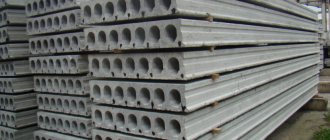
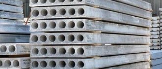
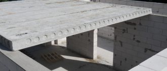
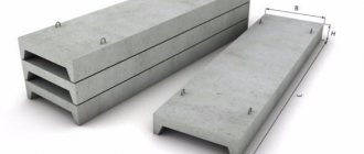
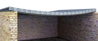
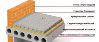
Reinforced concrete panels with cavities are used to construct floors between floors, as well as in the construction of private buildings. They are a connecting element in prefabricated and prefabricated monolithic buildings, ensuring their stability.
characteristic – load on the floor slab. It is determined at the building design stage. Before starting construction work, calculations should be performed and the load capacity of the base should be assessed.
An error in calculations will negatively affect the strength characteristics of the structure.
Load on hollow core slabs
Types of hollow core floor panels
Panels with longitudinal cavities are used in the construction of floors in residential buildings, as well as industrial buildings.
Reinforced concrete panels differ in the following characteristics:
- void sizes;
- shape of cavities;
- external dimensions.
Depending on the cross-sectional size of the voids, reinforced concrete products are classified as follows:
- products with cylindrical channels with a diameter of 15.9 cm. Panels are marked with the designation 1PK, 1 PKT, 1 PKK, 4PK, PB;
- products with circles of cavities with a diameter of 14 cm, made from heavy grades of concrete mix, are designated 2PK, 2PKT, 2PKK;
- hollow panels with channels with a diameter of 12.7 cm. They are marked with the designation 3PK, 3PKT and 3PKK;
- round-hollow panels with a cavity diameter reduced to 11.4 cm. They are used for low-rise construction and are designated 7PK.
Types of slabs and floor design
Panels for interfloor foundations are distinguished by the shape of the longitudinal holes, which can be made in the form of various shapes:
- circle;
- ellipse;
- octahedron.
By agreement with the customer, the standard allows for the production of products with holes whose shape differs from those specified. The channels can be elongated or pear-shaped.
Round hollow products also differ in size:
- length, which is 2.4–12 m;
- width in the range of 1m3.6 m;
- thickness of 16–30 cm.
At the request of the consumer, the manufacturer can produce non-standard products that differ in size.
Main characteristics of hollow core floor panels
Cavity boards are popular in the construction industry due to their performance characteristics.
Calculation of punching of interfloor slabs
Highlights:
- expanded standard range of products. Dimensions can be selected for each object individually, depending on the distance between the walls;
- reduced weight of lightweight products (from 0.8 to 8.6 tons). Weight varies depending on concrete density and dimensions;
- permissible load on the floor slab equal to 3–12.5 kPa. This is the main operational parameter that determines the load-bearing capacity of products;
- brand of concrete mortar that was used to fill the panels. Concrete compositions marked from M200 to M400 are suitable for production;
- the standard interval between the longitudinal axes of the cavities is 13.9-23.3 cm. The distance is determined by the size and thickness of the product;
- brand and type of fittings used. Depending on the standard size of the product, steel rods are used in a stressed or unstressed state.
When selecting products, you need to take into account their weight, which must correspond to the strength characteristics of the foundation.
How are hollow core slabs marked?
The state standard regulates product labeling requirements. The marking contains an alphanumeric designation.
Marking of hollow core slabs
It determines the following information:
- panel size;
- dimensions;
- maximum load on the floor slab.
The marking may also contain information on the type of concrete used.
Using the example of a product designated by the abbreviation PC 38-10-8, let’s look at the decoding:
- PC - this abbreviation means an interfloor panel with round cavities, made by the formwork method;
- 38 – product length, which is 3780 mm and rounded to 38 decimeters;
- 10 – rounded width indicated in decimeters, actual size is 990 mm;
- 8 is a number indicating how many kilopascals the floor slab can withstand. This product can withstand 800 kg per square meter of surface.
When performing design work, you should pay attention to the index in the product labeling to avoid errors. Products must be selected according to size, maximum load level and design features.
Advantages and disadvantages of cavity slabs
Floor slabs with cavities
Hollow slabs are popular due to their range of advantages:
- light weight. With equal sizes, they have high strength and successfully compete with solid panels, which have a lot of weight, accordingly increasing the impact on the walls and foundation of the building;
- reduced price. Compared to solid analogues, the manufacture of hollow products requires a reduced amount of concrete solution, which allows for a reduction in the estimated cost of construction work;
- ability to absorb noise and insulate the room. This is achieved due to design features associated with the presence of longitudinal channels in the concrete mass;
- increased quality of industrially manufactured products. The design features, dimensions and weight do not allow handicraft production of panels;
- possibilities for accelerated installation. Installation is much faster than constructing a solid reinforced concrete structure;
- variety of dimensions. This allows the use of standardized products for the construction of complex floors.
GENERAL INSTRUCTIONS
10.1. When calculating building structures based on deflections (bends) and displacements, the condition must be met:
(25)
where f is the deflection (bending) and displacement of a structural element (or the structure as a whole), determined taking into account the factors influencing their values, in accordance with paragraphs. 1-3 recommended applications 6;
fu is the maximum deflection (bending) and displacement established by these standards.
The calculation must be made based on the following requirements:
a) technological (ensuring conditions for normal operation of technological and handling equipment, instrumentation, etc.);
b) structural (ensuring the integrity of adjacent structural elements and their joints, ensuring specified slopes);
c) physiological (prevention of harmful effects and sensations of discomfort during vibrations);
d) aesthetic and psychological (providing favorable impressions from the appearance of structures, preventing the feeling of danger).
Each of these requirements must be met in the calculation independently of the others.
Limitations on structural vibrations should be established in accordance with the regulatory documents of paragraph 4 of recommended Appendix 6.
10.2. Design situations for which deflections and displacements, the corresponding loads, as well as requirements regarding construction lifting should be determined, are given in paragraph 5 of the recommended.
10.3. The maximum deflections of structural elements of coatings and ceilings, limited based on technological, structural and physiological requirements, should be counted from the curved axis corresponding to the state of the element at the time of application of the load from which the deflection is calculated, and those limited based on aesthetic and psychological requirements - from the straight line connecting supports for these elements (see also paragraph 7 of recommended Appendix 6).
10.4. Deflections of structural elements are not limited based on aesthetic and psychological requirements, if they do not worsen the appearance of the structures (for example, membrane coverings, inclined canopies, structures with a sagging or raised lower chord) or if the structural elements are hidden from view. Deflections are not limited based on the specified requirements for structures of floors and coverings above rooms with short-term occupancy of people (for example, transformer substations, attics).
Note. For all types of coatings, the integrity of the roofing carpet should, as a rule, be ensured by constructive measures (for example, the use of expansion joints, the creation of continuous coverage elements), and not by increasing the rigidity of the load-bearing elements.
10.5. The load reliability coefficient for all loads taken into account and the dynamic coefficient for loads from forklifts, electric vehicles, overhead and overhead cranes should be taken equal to unity.
Reliability coefficients for liability must be taken in accordance with mandatory Appendix 7.
10.6. For structural elements of buildings and structures, the maximum deflections and movements of which are not specified by this and other regulatory documents, vertical and horizontal deflections and movements from constant, long-term and short-term loads should not exceed 1/150 of the span or 1/75 of the cantilever overhang.
An example of calculating the deformation of a reinforced concrete slab as a beam of variable section
The deflection of the slab with the selected design scheme will be
f = k5ql 4 /384EI p
(321.1)
As you can see, the formula is quite simple and differs from the classical one by the presence of an additional coefficient. Coefficient k takes into account the change in the height of the compressed section area along the length of the beam under the action of a bending moment. With a uniformly distributed load and concrete operating in the region of elastic deformations, the value of the coefficient for approximate calculations can be taken k = 0.86. Using this coefficient allows you to determine the deflection of a beam (slab) of variable cross-section, as for a beam of constant cross-section with height h min. Thus, in the above formula there are only 2 unknown quantities left - the calculated value of the modulus of elasticity of concrete and the moment of inertia of the reduced section I p in the place where the height of the section is minimal. All that remains is to determine this very moment of inertia, and we will take the elastic modulus equal to the initial one.
For clarity, further calculations will be made for the slab mentioned above.
Theoretical premises and assumptions taken when determining the deflection of a reinforced concrete slab operating in the area of elastic deformations
1. Since the ratio of the length of the slab to the height is l/h = 560/20 = 28, i.e. is significantly greater than 10, then the influence of transverse forces on deflection can be ignored.
2. The beam (slab) consists of materials with different elastic moduli, so the neutral line - the axis of the beam will not pass through the centers of gravity of the cross sections, but will be shifted and will pass through the reduced centers of gravity. The position of the given centers of gravity will depend on the ratio of the elastic moduli of concrete and reinforcement.
3. Since the modulus of elasticity of steel is significantly greater than the initial modulus of elasticity of concrete, when considering the geometric parameters of the cross-section of the slab as a single section, the cross-sectional area of the reinforcement should be multiplied by the ratio E s / E b. For a slab this ratio will be a s1 = 2000000/245000 = 8.163
A manual for the design of residential buildings. Vol. 3. (to SNiP 2.08.01-85) COLORS
Calculation of reinforced concrete floor slabs based on limit states of the second group6.39.
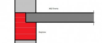
Prefabricated slabs that do not have special connections to ensure the continuity of the floors on supports are calculated according to the limit states of the second group as simply supported. When the floors are pinched by walls, if cracks do not form on the supports, and also in the presence of special connections that ensure the continuity of the floors on the supports, it is allowed to consider two stages of their operation when calculating slabs based on the limit states of the second group: before and after pinching.
Calculations based on the limit states of the second group before pinching of the slab are performed under the assumption that it is freely supported. For this stage, the possibility of cracks forming in the span of the slabs is checked and their short-term opening from loads applied before the slab is pinched is determined. When calculating, the loads from the own weight of the slab and the prefabricated elements resting on it (floor slabs, panel partitions, sanitary cabins, etc.) installed before the installation of the slabs of the next floor are taken into account, as well as the temporary load from the weight of the installation equipment (struts, conductors) etc.), containers with solution or materials stored on the ceiling. It is recommended to take a temporary installation load of at least 0.5 kN/m2 (50 kgf/m2).
For the second stage of slab operation, short-term deflections from the load applied after pinching the slab are determined (partitions made of piece materials, floors, temporary loads), and the increment in deflections from all long-term loads caused by the development of creep deformations in the concrete of the slab, and also check the possibility of crack formation in span and on supports from total loads. If cracks form on the supports in the absence of special connections designed to absorb bending moments in the supporting sections, the slab is calculated as simply supported. When cracks form in the span, their opening under long-term load is checked.
When calculating prefabricated slabs taking into account pinching on supports, it is recommended to take into account the final rigidity when rotating the support fasteners.
6.40.
For monolithic slabs, all loads can be considered applied after the formwork is removed.
Prefabricated shell slabs of prefabricated monolithic floors are allowed to be checked by calculation according to the limit states of the second group only for installation. To reduce their deflections and prevent the formation of cracks until the monolithic concrete reaches its design strength, it is recommended to use temporary telescopic supports. For the installation of prefabricated shell slabs, it is recommended to use lifting schemes that do not lead to the formation of cracks.
A prefabricated monolithic floor, after the concrete has reached its design strength, is calculated in the same way as a monolithic floor.
6.41.
When determining the deflections of floor slabs, the load from the weight of non-load-bearing panel external walls and partitions is taken according to clause 6.25.
Concentrated loads from external walls and partitions can be replaced by a uniformly distributed load equivalent in magnitude to the bending moment in the floors.
6.42.
When calculating floor slabs based on the limit states of the second group, the following loads are distinguished:
qn
standard load, which is used to check the formation of cracks in the slab;
ql is
the standard long-term load, which is used to check deflections and crack openings;
q 1 -
load applied to the slab before it is pinched (taking into account two stages of slab operation);
q 2
- the same, after pinching the plate.
When determining the load qn
the full value of the live load is taken into account, equal to 1.5 kN/m2 (150 kgf/m2) for apartments in residential buildings.
When determining the load q 1,
only the long-term part of the live load is taken into account, equal to 0.3 kN/m2 (30 kgf/m2).
Loads q1
,
q2
are determined according to clause 6.39.
All loads are determined with a load safety factor equal to 1.
6.43.
Deflections and opening of cracks in a slab bending out of plane in two directions can be determined approximately by linear interpolation of the deflections corresponding to the load at which cracks form in the slab
qcrc
and the ultimate load
q ser,
determined based on the characteristics of the slab material for the second limit states groups. For a slab calculated taking into account two stages of work (before and after pinching), when determining deflections and crack openings, it is necessary to distinguish between cases when cracks form before and after pinching of the slab.
Calculation of reinforced concrete slabs based on the formation of cracks
6.44.
The formation of cracks is checked for the section in the middle of the span
l1
of the slab, and for slabs clamped by walls, also for the supporting sections.
6.45.
For a prefabricated simply supported slab, the load
qcrc
at which cracks form in it in the span is determined by the formula
qcrc
=
Mcrc
/(
a1 l21 l2
), (213)
where Mcrc
— bending moment corresponding to the formation of cracks in the design section of the slab;
for prestressed slabs, the value of Mcr
c is calculated taking into account the influence of prestressing reinforcement on the moment of crack formation;
a1
is the coefficient determined for slabs supported on four and three sides (Fig. 48 and 49);
for a slab supported on two opposite sides, coefficient a1
= 0.125.
For precast slabs calculated taking into account two stages of work (before and after pinching), load qcrc
and
q оcrc,
at which cracks form in the span and on the support, respectively, are recommended to be calculated using the formulas:
(214)
(215)
where q1
- load applied to the slab before it is pinched;
a2
,
a3
- coefficients determined for slabs supported on four and three sides, according to the graphs in Fig.
48 and 49; for a slab supported on two opposite sides, a2
= 0.0417;
a3
= 0.0833;
a
is a coefficient taking into account the elastic compliance of pinching,
(216)
Kj
— coefficient of support rigidity when turning, calculated for a platform joint using the formula
(217)
Eip
— bending rigidity of the floor slab when bending along the span
l1
;
d is
the length of the slab along the support;
bpl,1
,
bpl,2 -
depths of the floor slab support areas, respectively, for the upper and lower mortar joints;
lm ,1
,
lm,2
- compliance coefficients during compression of the upper and lower mortar joints, respectively, determined by adj.
2; Mocrc
is the bending moment at which cracks form in the supporting section of the slab.
If q оcrc
<
qп
, then the slab is calculated as simply supported.
Rice. 48. Coefficients for slabs simply supported along the contour
Rice. 49. Coefficients for slabs simply supported on three sides
6.46.
For a monolithic slab of continuous cross-section, the load
qcrc ,i
, at which cracks form in
the i
-th section of the slab (see Fig. 45), is determined by the formula
qcrc,i
=
aoi h2 Rbt
, (218)
where aoi
is
a coefficient determined depending on the aspect ratio of the slabs and the clamping pattern according to the table. 13.
Table 13
Supporting the slab
| Aspect Ratio | Odds | ||||
| l = | ao1 | ao2 | ao3 | bo | |
| Pinching by | 1 | 5,6 | 5,6 | 9,4 | 0,3 |
| contour | 1,11 | 5 | 5,2 | 8 | 0,31 |
| 1,25 | 4,3 | 4,9 | 6,8 | 0,31 | |
| 1,43 | 3,9 | 4,7 | 6 | 0,31 | |
| 1,66 | 3,6 | 4,6 | 5,3 | 0,31 | |
| 2 | 3,5 | 4,6 | 4,9 | 0,32 | |
| Pinching in three | 0,7 | 3,3 | 4,3 | 5,6 | 0,26 |
| parties | 0,8 | 3,3 | 4,2 | 5,1 | 0,33 |
| 0,9 | 3,3 | 4,2 | 4,9 | 0,33 | |
| 1 | 3,3 | 4,2 | 4,8 | 0,34 | |
| 1,2 | 3,4 | 4,2 | 4,7 | 0,32 | |
| 1,5 | 3,4 | 4,2 | 4,6 | 0,32 | |
Calculation of deflections of reinforced concrete slabs
6.47.
Deflections of slabs simply supported on both sides are determined according to the design standards for reinforced concrete structures. Maximum deflections from long-term loads of slabs freely supported on three or four sides with corners fixed from lifting can be determined using the formulas:
in the case where cracks do not form, qcrc
>
qn
f =
jb2 l41b1 ql
/(
jb1 Eb h3
), (219)
where b1
— coefficient calculated from the graphs in Fig.
50, 51 depending on the slab support pattern; ql
is the long-term load against which the deflection of the slab is checked;
Eb
is the initial modulus of elasticity of the concrete slab;
h
is the thickness of the slab;
Rice. 50. Coefficients bi
for slabs simply supported along the contour
Rice. 51. Coefficients bi
for slabs simply supported on three sides
in the case where cracks form under load ( qcrc
<
ql
),
f
=
jb2 fcrc
+ (
f ser
—
jb2 fcrc
) (
ql qcrc
)/(
qser qcrc
), (220)
where fcrc
is
the short-term deflection under load
qcrc
corresponding to the moment of crack formation in the slab;
(221)
jb1
- coefficient taking into account the influence of short-term creep of concrete and determined for concrete: heavy, light with dense fine aggregate - 0.85;
light with porous fine aggregate - 0.7; jb2 -
coefficient taking into account the influence of long-term creep on the deformation of an element without cracks, determined according to SNiP 2.03.01-84: for heavy, light and cellular concrete with
w
equal to 40 - 75% (ambient air humidity),
jb2
= 2, at
w
below 40%
jb2
= 3;
fser is
the deflection of the slab in the limit state from long-term loads, calculated based on the design characteristics of concrete and reinforcement, for limit states of the second group
(222)
Rs,ser
— design resistance for limit states of the second group of slab reinforcement located along span
l1
;
Es1
is the modulus of elasticity of the reinforcement located along the span
l1
;
ho1
is the working height of the section when the slab is bent along the span
l1
;
m
is the reduced reinforcement coefficient,
m
= (
m1 n2j
+
m2
)/(1 +
n2j
), (223)
m1
,
m2
are reinforcement coefficients (the ratio of the cross-sectional area of the reinforcement to the area of the entire section), respectively, along spans
l1
and
l2
;
nj
cotangent of the angle of inclination of the fracture line, accepted for slabs supported on four sides, as well as on three sides for l £ 1 equal to 1, and for l > 1 - determined according to the instructions in paragraph 6.27;
n
is a coefficient characterizing the elastic-plastic state of concrete in the compressed zone, adopted according to SNiP 2.03.01-84.
With prolonged exposure to loads for structures made of heavy and light concrete at an ambient air humidity of 40 - 75% n
= 0.15;
below 40% n
= 0.l;
x = 0.1 + 0.5 m Rs,ser
/
Rb,ser
, (224)
h1
— coefficient taking into account possible deviations in the thickness of the protective layer of reinforcement; for contour-supported mesh-reinforced slabs with a thickness of less than 16 cm
h1
=
ho1
/(
ho1
- 0.7), (225)
but not more than 1.2; in other cases it is accepted according to SNiP 2.03.01-84. In formula (225), the value ho1
taken in cm.
h2
is a coefficient that takes into account the discrepancy between the maximum deflection of the slab and the deflection at the point of intersection of the break lines and is determined by the formulas:
for contour supported slabs
h2
= 1 + 0.2(
l2
/
l1
1); (226)
for slabs supported on three sides
at l2
³ 0.5
l1
,
h2
= 1 + 0.2(2
l2
/
l1
1); (227)
at l2
£ 0.5
l1
,
h 2
= 1 (1 2
l2
/
l1
)2; (228)
qser
is
the maximum load on the slab, calculated in clause 6.27 using the design characteristics of reinforcement and concrete for the limit states of the second group;
in the case where cracks form under load qcrc
³
qn
,
f
=
f crc
(
jb2ql qn
+
qcrc
)/
qcrc
+ (
fser fcrc
)(
qn qcrc
)/(
qser qcrc
), (229)
where fser
is
calculated using formula (222) with n = 0.45.
6.48.
The maximum deflections from long-term loads of prefabricated slabs, calculated taking into account two stages of their operation (before and after pinching), can be determined using the formulas:
in the case when cracks do not form in the span ( qcrc
>
qn
)
,
then
f
=
jb2 l41
[
b1 ql a
(
ql q1
)(
b1 b2
)]/(
jb1 Eb h3
), (230)
where b1
,
b2
- coefficients determined from the graphs in Fig.
50, 51; a
is a coefficient that takes into account the pinch compliance of the slab and is determined by formula (216);
q1
is the load at which elastic pinching of the slab occurs;
in the case when cracks in the span form before elastic pinching of the slab, q1
³qcrc
f _
=
jb2 fcrc
+ (
fser jb2 fcrc
)(
ql qcrc
D
q
)/(
qser qcrc
), (231)
where fcrc
— calculated using formula (221);
fser
- calculated using formula (222);
Dq _
=
a
(
ql q1
)(1
b2
/
b1
); (232)
in the case when cracks in the span form after elastic pinching of the slab, q1
<
qcrc
f
=
jb2
[
focrc
+ (
fser focrc
)(
ql qocrc
)/(
q ser qocrc
), (233)
Where
focrc
= [
b1 qocrc
(
qocrc ql
)(
b1 b2
)
a
]
l41
/(
jb1 Eb h3
), (234)
qocrc
- load at which cracks form in the span in the clamped slab.
6.49.
For monolithic slabs clamped along the contour or on three sides, the maximum deflection is determined by the formulas:
in the case when cracks do not form in the span ( qcrc
³
qn
)
f
=
jb2 b2 ql l41
/(
jb1 Eb h3
); (235)
in the case when cracks in the span form under load qcrc
<
ql
,
f
=
focrc
+ (
foser focrc
) (
ql qcrc
)/(
q ser qcrc
), (236)
where focrc
- deflection of the clamped slab at the moment of crack formation in the span, determined by the formula
focrc
=
b2 qcrc l41
/(
jb1 Eb h3
); (237)
foser
- deflection of the clamped slab in the limit state from long-term loads, calculated based on the design characteristics of concrete and reinforcement for limit states of the second group
foser
=
fse r
0, (238)
where fse r
— calculated using formula (222); 0 is a coefficient that takes into account the effect of pinching the slab on its deflections in the limit state and is determined from table. 14 depending on the value
(239)
yi
— coefficients characterizing the orthotropy of the slab reinforcement (see clause 6.36);
n
is the number of pinched sides of the slab;
Table 14
| Slab diagram | Coefficient 0 |
| 0 = 1/(1 + y / | |
| 0 = (1 + 0,25y / |
in case cracks form under load qсrс
, satisfying the conditions that
ql
<
qсrс
£
qn
f
= [
focrc
+ (
foser focrc
) (
qn qcrc
)/(
q ser qcrc
)]
ql
/
qn
. (240)
Crack opening calculation
6.50.
The opening width of cracks in reinforced concrete slabs is determined according to SNiP 2.03.01-84 depending on the value of stress
ss
in the tensile reinforcement in the section with the crack.
For slabs supported along the contour and on three sides, the stress can be determined using the formulas:
at ql
>
qcrc
ss
=
ss,crc
+ (
Rs,ser ss,crc
)(
ql qcrc
)/(
q ser qcrc
); (241)
at ql
£
qcrc
<
qn
ss
= [+ (
Rs,ser ss,crc
)(
qn qcrc
)/(
q ser qcrc
)]
ql
/
qn
, (242)
where ss,crc
— stress in the reinforcement immediately after the formation of a crack in the section
(243)
Mcrc
— bending moment at which cracks form in the section under consideration;
x
- calculated using formula (224).
6.51.
In weakly reinforced slab sections with
m
£ 0.8%, the calculated value of crack opening can be reduced by multiplying by the coefficient
w
, which takes into account the work of tensile concrete over cracks,
w = w1w2
£ 1, (244)
where w1
coefficient taking into account the load level
(245)
mn
,
ml
is the bending moment acting in the section of the slab, respectively, from the load
q n
and
q l
:
mn
=
mcrc
+ (
mser mcrc
)(
qn qcrc
)/(
qser qcrc
); (246)
ml
=
mcrc
+ (
mser mcrc
)(
ql qcrc
)/(
qser qcrc
), (247)
mser -
limiting moment perceived by the slab section;
determined with the characteristics of concrete and reinforcement corresponding to the limit states of the second group; mo
- the moment at which the stretched concrete above the cracks practically stops working:
(248)
Wo
— elastic moment of resistance of the section during bending;
s = 100 N/cm2 - compressive stress; y2
is a coefficient taking into account the duration of the load;
y2
= l.8
mcrc
/
mn
³ 1; (249)
for mo
< mn
the coefficient
y2 =
1
.
Calculation of floor slabs for installation impacts
6.52.
For installation of floor slabs, it is recommended to provide statically definable lifting patterns. The distribution of forces from the slab's own weight at the points where it is suspended from the mounting crossbeam is determined by the design of this crossbeam, which is made in the form of a lever mechanism or a system of rotating blocks.
Floor slabs and mounting equipment for lifting them in a horizontal position should be designed based on the condition that the projection on the surface of the slab of its center of gravity and the crane hook must coincide. This condition applies to symmetrical and asymmetrical products.
The use of statically indeterminate lifting systems (traverses with four slings permanently attached to a ring) is allowed only for slabs up to 2 m wide, supported on the short sides. In this case, the slab is calculated as suspended on two loops located diagonally.
6.53.
When designing a lifting system and placing mounting loops or holes, you should strive to ensure that the bending moments from installation influences do not exceed the moments from the full standard load. If this condition cannot be met, then when calculating the deformations of the slab during the operational stage, one should take into account the decrease in their rigidity as a result of the short-term action of installation loads in cases where they cause the appearance of cracks.
- For mounting (lifting) hinges of floor slabs, only hot-rolled reinforcing steel of class A-I should be used.
- Depending on the static force per loop, its diameter is taken according to the table. 15.
Table 15
| Loop diameter, mm | Limit static force per slab, kN (kgf) | Loop diameter, mm | Limit static force per slab kN (kgf) |
| 6 | 1 (100) | 18 | 25 (2500) |
| 8 | 3 (300) | 20 | 31 (3100) |
| 10 | 7 (700) | 22 |
