4.2.7. Calculation of transverse reinforcement of the crossbar
The purpose of the calculation is to determine the diameter and pitch of transverse rods (clamps) in welded reinforcement frames.
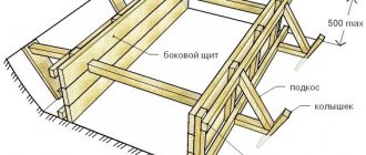
The calculation is performed from the condition of the strength of the inclined sections of the crossbar under the action of the transverse force Q in accordance with the Standards [1, clauses 3.29¸3.32]. In this case, the design sections must be taken in places where the greatest lateral forces are applied (within each span), as well as in places where the pitch of the clamps changes (that is, at a distance of 0.25loi
from supports within each span). For example, in a three-span crossbar, these should be sections in which transverse forces QA,max, QB,maxleft, QB,maxright act, and also located at a distance of 0.25lo1, 0.75lo1 in the first span and at a distance of 0.25lo2 from the support in the second span .
It is allowed in the last three design sections (that is, in places where the clamp pitch changes) to only check the strength against the action of the transverse force Qi, which acts in the marked places, and not calculate the required clamp pitch. In this case, the pitch of the clamps
| in the middle zone along the length of the crossbar, you should first | accept in accordance with |
| requirements of the Standards [1, clause 5.27]. If the check shows that | the strength condition is not |
is satisfied, a slightly greater distance than 0.25×loi should be retreated from the support until the strength condition is met at the appropriate value of the shear force Qi. The place found in this way will be the place where the step of the clamps changes, which meets the Norm condition, that is, it is located at a distance of 0.25 × loi from the support. Unlike the task of calculating the required clamp spacing, this task is simpler, which is why it is proposed for the marked locations.
Calculation of the required spacing of clamps for the support sections of the crossbar must be performed according to the algorithm in Table. 3.5 sequentially under the action of each specified lateral force:
QA,max, QB,maxleft, QB,maxright.
4.2.8. Design of a crossbar
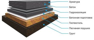
The design of the crossbar is carried out using a diagram of materials, which allows you to rationally position the longitudinal reinforcement along the length of the crossbar in accordance with the enveloping moment diagram.
The purpose of constructing a diagram of materials is to find places where part of the longitudinal rods of the structure break in accordance with the envelope (enveloping) diagram of moments, that is, those places where they (part of the rods) are no longer required by strength conditions.
The construction of a diagram of materials is carried out on a graph paper of A3 format, where comprehensive diagrams of moments and shear forces must first be constructed.
Due to the fact that in the course project it is recommended to assemble a symmetrical crossbar, then for a three-span crossbar a diagram of materials can be constructed for one and a half spans, and for a two-span crossbar - for one span. The reinforcement of a multi-span crossbar is also made symmetrical relative to the axis of symmetry along the length.
| Should have in | I see that the diagram of materials is being built | graphic-analytical |
| method, that is, part | its parameters are calculated analytically, | the other is located |
studfiles.net
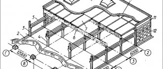
Design of crossbars
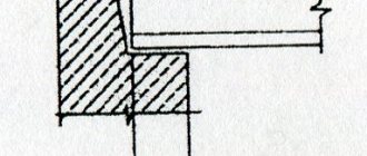
Prefabricated crossbars, as a rule, are made with shelves for supporting floor slabs on them so that the top of the slabs approximately coincides with the top of the crossbar. This arrangement of shelves increases the weight of the crossbars compared to crossbars designed to support the slabs on top. However, this reduces the height of the floors, which leads to savings on walls, partitions, stairs and operating costs with the same floor heights “in the clear”.
However, for frames of open shelving for technological equipment, where the height of the structure does not matter, crossbars of a rectangular section or T-section with a shelf in the upper zone are used, which make it possible to reduce the influence of torsion under one-sided load.
Prefabricated crossbars with spans of 6 m or more, as a rule, are designed with prestressed lower reinforcement, and for smaller spans - with non-prestressed reinforcement. For light loads, typical of public and residential buildings, crossbars with a span of 6-7 m can also be with non-stressed reinforcement.
The crossbars of monolithic floors are designed as a rectangular section with slabs or secondary beams monolithically connected to them. The reinforcement in such crossbars is most often stress-free.
If the height of the cross-section of the cross-bar is more than 700 mm, longitudinal rods with a diameter of 8-10 mm should be installed at the side edges with a distance between them of no more than 400 mm.
Transverse reinforcement of crossbars is usually vertical clamps (transverse rods). In this case, their pitch in individual sections is assumed to be different, with an increase from the support to the middle of the span (with a decrease in the lateral force).
Clamps, as a rule, are taken in the form of 2-3 flat welded frames connected at the top and bottom with horizontal rods. Moreover, if there are noticeable torques (for example, in the outer crossbars or with design loads in adjacent spans that differ by more than 2 times), these rods are welded to the longitudinal rods by spot welding with welding tongs or using staples welded to the clamps of an arc welding with extended seams with a length of at least 6dw. In the absence of conditions for welding, as well as with knitted spatial frames, vertical and horizontal clamps must be bent with an overflow of at least 30dw.
In the absence of noticeable torsion, the horizontal connecting rods can either be spot welded to the vertical rods or tied to the longitudinal rods in the form of studs (Fig. 7.25). In the latter case, the mounting rigidity of the frame should be ensured by welding oblique rods, strips, etc. In addition, connecting rods can also be welded to the longitudinal rods of the frame using spot tacks (type KZ according to GOST 14098-91) in compliance with a technology that prevents burning of the longitudinal rods.
Spatial reinforcement cages in the absence of torsion
a - with connecting rods welded to vertical rods; b - with studs tied to longitudinal rods; 1 — hairpin
The pitch of the connecting rods may exceed the pitch of the clamps, but should not exceed 600 mm.
Longitudinal rods of welded and knitted frames are accepted with a diameter of no more than 0.8 of the diameter of the clamps.
The location of the bends, determined by the diagram of bending moments in the crossbar
1 - diagram of materials; 2 - envelope diagram of moments
Clamps supplied according to calculations must have a pitch of no more than 0.5/g0 and no more than 300 mm. In places where the strength of inclined sections can be ensured by concrete alone (i.e. at Q≤0.5Rbtbh0), the spacing of the clamps can be increased to 0.75/g0, but not more than 500 mm.
If, when calculating the span sections of crossbars, the upper compressed reinforcement is taken into account, then to prevent its bulging, the stirrups, as well as the upper connecting horizontal rods, should have a pitch of no more than 15 d, where d is the diameter of the compressed rods.
For monolithic crossbars, bends of longitudinal upper or lower reinforcement can also be used as transverse reinforcement. The beginning of the bend in the stretched zone must be at least 0.5h0 from the normal section in which the bending rod is used according to calculation, and the end of the bend must be located no closer than the normal section in which the bend is not required according to calculation (Figure above) .
ros-pipe.ru
Reinforcement of column consoles with hinged support of the crossbar
The fire resistance limit of columns is at least four hours.
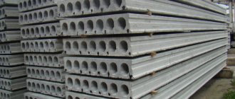
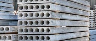
Crossbars, depending on their location, are divided into three groups: ordinary, end and at expansion joints, staircases. The range of crossbars for floor slabs made of ribbed slabs contains crossbars with a section height of 600 mm and a length of 8560, 5560 and 2560 mm for spans of 9.6 and 3 m, respectively. The range of crossbars for floors made of hollow-core slabs contains crossbars with a height of 450 mm for spans of 3.6 and 7.2 m, and also with a height of 600 mm for a span of 9 m (see figure above).
For ceilings made of type 2T slabs 12 m long, crossbars 600 mm high with a span of 6 m are provided.
The frame frame uses crossbars with a height of 600 mm with two options for ridge heights of 230 or 300 mm (depending on the type of slabs used for hollow-core or ribbed interfloor slabs).
Prestressed crossbars are usually made of heavy concrete of classes B22.5-B40. Thermally strengthened bar steel of periodic profile of class At-V is used as prestressing reinforcement.
In the absence of the specified steel, it is possible to use crossbars with prestressed working reinforcement of class A-IIIb, as well as At-Vck and non-prestressed At-IIIc. The reinforcement is tensioned either mechanically or electrothermally.
The crossbars are calculated according to the scheme of a single-span beam with hinged supports for a vertical design uniformly distributed load, taking into account the tension that occurs when they work as part of the floor disk. The tensile force value is assumed to be 8 tf.
The permanent load includes loads from the self-weight of the slabs with grouted joints, the weight of the floor and the weight of the partitions.
Calculation of crack resistance and deformation during the operation stage is carried out taking into account the joint operation of the crossbar with the floor slabs, and all loads are assumed to be long-term.
End crossbars, stair bolts and those located at the expansion joint are designed for torsion; ordinary to the action of uniformly distributed loads, the magnitudes of which in steps adjacent to the crossbar differ by no more than two times; in this case, a one-sided uniformly distributed load on the crossbar should not exceed half of the full design load, otherwise it is necessary to perform torsion calculations.
The shelves of the crossbars are designed for the load from the slabs, which is taken one step higher than the load for which the crossbar itself is designed (except for the crossbars for a load of 18.0 tf/m). The load-bearing capacity of the crossbar flanges takes into account the possibility of applying local loads from the floor slabs to a level higher than the load for which the crossbar itself is designed. In this case, the sum of uniformly distributed loads, per linear meter of the length of the crossbar flange, should not exceed the full design load on the crossbar. The principal reinforcement of the crossbar support zone is shown in Fig. below.
Presentation on the topic: Fig. 15.14. Crossbar reinforcement
1 – points of theoretical breakage of working rods 7 in the span; 2 – the same working rods 3 on the support; 3 – working rods on the support; 4 – clamps; 5 – butt embedded parts on the support; 6 – trimming fittings; 7 – working rods in span
Rice. 17.15. Schemes of forces at the joint of crossbars
a – conditional; b – calculated; 1 – columns; 2 – crossbars
There are 2 types of joints: hinged and rigid.
In practice, a hinged joint is widely used due to its ease of manufacture and installation compared to a rigid one.
Rice. 15.16. Hinged joint of crossbars
1 – joint strip; 2 – embedded plates on top of the crossbar; 3 – embedded plates of the column; 4 – inventory mounting angles; 5 – embedding seam; 6 – anchor bolts
In residential construction, a non-cantilevered rigid joint of crossbars is used (using an assembly table made of channels). Such a joint completely absorbs transverse forces with concrete dowels formed when the joint is grouted.
Rice. 17.17. Rigid non-cantilever joint of crossbars
a – general view; b – side view; 1 – outlets of the lower reinforcement; 2 – embedment concrete; 3 – outlets of the upper reinforcement; 4 – issues
from a column of butt rods; 5 – lower embedded part of the column; 6 – mounting table made of channels; 7 – keyways
The rigid joint of the crossbars, combined with the joint of the column, simplifies and reduces the cost of installation, because reduces the number of mounting units. The main disadvantage is the high metal consumption.
Rice. 15.18. Combined joint of crossbars and columns
1 – steel plate; 2 – welding; 3 – embedding seam; 4 – mounting angles; 5 – mortgages
details
Calculation of short consoles
Rice. 15.19. Column console reinforcement
Punching calculation
The calculation for punching of slab structures (without transverse reinforcement) should be made from the condition
F Rbtum h0
where F is the pushing force;
- coefficient taken equal for concrete:
| heavy | 1,00 |
| fine-grained | 0,85 |
| lung | 0,80 |
um is the arithmetic mean of the perimeters of the upper and lower bases of the pyramid formed during punching within the working height of the section.
Reinforcement of the crossbar support area
Crossbars have embedded products for welding ribbed or bonded hollow-core slabs. Reinforcement of the support and span sections of the crossbars allows them to be used in non-aggressive, weakly and moderately aggressive environments. In the upper part of the crossbar, there are keys on the side surfaces to ensure that the crossbar works together with the floor slabs.
The fire resistance limit of the crossbars is at least two hours.
Connections and diaphragms. Vertical abutments of the braced frame are selected in each project depending on space-planning decisions and construction conditions. Abutment designs can be standard, individual using standard structures, or completely individual. In braced frames, braced panels formed by working together “braced” columns and stiffening diaphragms or floor-cut steel braces installed in the span between the columns are recommended as abutments.
The nomenclature of stiffening diaphragms provides (see figure above) double-flange diaphragms used to support floor slabs on them on both sides, and single-flange diaphragms for supporting slabs on them on one side, as well as in the direction perpendicular to the direction of the crossbars. Rigidity diaphragms can be solid or with openings.
Steel connections are made from two equal-angle angles that make up a T-shaped section; Triangular cross braces of a U-shaped cross-section with a junction “in the girth” of the column have also been developed (see figure above).
Longitudinal connections are installed in a six-meter span between the columns, transverse connections in spans of 6 and 9 m.
For the construction of earthquake-resistant buildings for interspecific purposes, instead of the IIS-04 series, the 1.020.1-2C series was developed and implemented. The series is used in areas with seismicity of 7, 8 and 9 points.
Nominal crossbar spans in the transverse direction 3.0; 6.0; 7.2 and 9.0 m; in longitudinal 6.0; 7.2; 9.0 and 12.0 m. Design load on crossbars is up to 145 kN/m.
Floor heights: 2.8; 3.0; 3.3; 3.6; 4.2; 4.8; 5.4; 6.0 and 7.2 + +nx6.0 m.
The columns have a single cross-section of 400×400 mm with outlets for reinforcement and steel corners of the consoles for supporting the crossbars. The crossbars are designed with a height of 450 and 600 mm of T-section with shelves for supporting floor slabs (hollow-core and ribbed) with heights of 22 and 30 cm or type 2T. The upper zone of the crossbars is designed with exposed transverse reinforcement along the entire length or in the supporting sections, into which longitudinal reinforcement is installed during installation and concreted after welding.
Series 1.020-1/83
–
Design of a frame for interspecific use for multi-storey public buildings, production and auxiliary buildings of industrial enterprises.
One of the most voluminous standard series, which is a support for designers who work with frame housing construction. Series 1.020-1/83
consists of more than 30 issues, which include the main load-bearing structures of buildings: crossbars, stiffening diaphragms, columns and reinforced concrete glass foundations. The main vertical load-bearing element of a frame building, which determines the height of the floor, is a reinforced concrete column; it is this column that is installed in the foundation of the glass structure and withstands all the loads of the building frame. The quality of the column must be impeccable. More than a dozen standard albums of the 1.020-1/83 series are devoted to its reinforcement and design drawings.
Composition of series 1.020.1/83
Modern prefabricated reinforced concrete is manufactured according to GOST standards and standard drawings. A significant part of the standard is occupied by technical requirements for the production and quality control of concrete products. Thus, double-flange crossbars, columns and ribbed floor slabs are tested with control loads for strength, rigidity and crack resistance.
The nomenclature of series 1.020.1/83 includes:
- Single-shelf crossbars;
- Double-shelf crossbars RDR;
- Columns with a section of 400x400 mm;
- Foundations (pillars).
Reinforced concrete crossbars
According to their design, crossbars are divided into products that support ribbed slabs and crossbars for flat slabs. These are different in load-bearing capacity and product format. Single-flange crossbars have an L-shaped cross-section, double-flange crossbars have an inverted T. Working drawings and diagrams of crossbars can be found in the standard album; you can download series 1.020.-1/83 on our website for free. If you wish, you can also buy reinforced concrete columns and foundations, crossbars and floor slabs with delivery throughout Russia. Our delivery is valid all seasons throughout Russia. Crossbars with a height of 450, 600 mm are recommended for buildings with spans of 3.6, 7.2 and 9 meters. These are the most common standard designs for various buildings, so this type of reinforced concrete can be called the best-selling. If you want to calculate the crossbars, you need to download series 1.020-1/83 and familiarize yourself with the reference tables. Experts are always happy to help you with choosing the type of crossbar. According to your order, crossbars according to series 1.020.1/83 can be produced with individual adjustments.
Reinforced concrete columns
Columns of various types are used as the vertical foundation of buildings; they are mounted with appropriate column supports and monolithic. Modern reinforced concrete columns are manufactured based on many strict rules. Preservation of shape and load-bearing capacity is ensured by reinforcement cages made of prestressed steel. Issues 2-3, 2-5, 2-13 of series 1.020.1/83 include hundreds of drawings of columns of various types - upper, middle, lower. Depending on their position in the building frame, reinforced concrete columns are divided into rows: columns in the middle rows and columns in the outer rows.
Columns can be prefabricated or jointless, with consoles of various floor cuts. Prices for columns are determined depending on the consumption of steel and concrete, and the frost resistance and water resistance of concrete is set individually. On our website you can leave a request for columns and receive products that are produced specifically for your facility. Increased load-bearing capacity or anti-corrosion protection class - you can get all this upon request. Massive and large-sized columns are quite difficult to deliver, so you should trust only professionals who will quickly and carefully deliver columns series 1.020.1/83 to your facility or warehouse.
Series 1.020-1/83
determines the production of crossbars with spans of 3-9 meters for supporting hollow-core and ribbed floor slabs, including TT slabs and slabs with holes.
Such crossbars can be universally used to implement almost any solution. These are single-shelf and double-shelf crossbars. These are issues
3-1, 3-2, 3-3, 3-4, 3-5, 3-6, 3-7, 3-8 and 3-9 of series 1.020-1/83. The reinforcement of the crossbars is also defined in the series, drawings of welded frames and meshes are analyzed in detail.
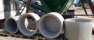
Glass foundations for columns are made for standard sections of supporting structures 300x300 and 400x400 mm. They are determined by episode 1-1 1.020-1/83.
Reinforced concrete glasses are traditional structures for supporting columns of industrial and residential buildings.
Rigidity diaphragms are large-format products that are used for the construction of industrial buildings. Their production is determined by the series 1.020-1/83 issue 4-1 and issue 4-2.
The complex reinforcement of these products, their bulkiness and poor transportability reduce the scope of application of diaphragms.
In addition to defining the requirements for the production of columns and crossbars, series 1.020-1/83 includes definitions of steel connections for columns with different floor heights, assembly units and connecting steel products. You will find this in issues 5-1, 6-1 and 7-1 of series 1.020-1/83.