Concept, features and system of information sources
Hatching is a symbolic symbol for building materials. Most often used when working with concrete. The drawing is drawn with a pencil and consists of dots, lines, and strokes intersecting or located at a certain distance. Schemes are used in most construction projects. However, there are features:
- if necessary, shading may not be created at all or may be created partially to highlight individual objects;
- If necessary, additional drawings with explanations are used for materials that are not provided for in the standard.
In construction, there are three systems of markings based on shading:
- GOST 3455 - 59;
- GOST 2.306 - 68;
- GOST R 21.1207-97.
Consider in detail each type, which has its own characteristics of applying symbols.
Standard GOST 3455 - 59
This template was used from January 1, 1959 to January 1, 1971. Its well-known title was “Drawings in mechanical engineering. Hatching in sections and sections.” The notation system was as follows:
- metal – designation in the form of oblique strokes between which there is an equal interval;
- other non-metallic objects - left and right inclined lines intersecting at right angles;
- tree: pattern of a sectional section - an image similar to the texture of larch; cross-section drawing - an image of cracks, as well as rings of a tree trunk;
- unreinforced concrete - schematic drawing of sand gravel;
- reinforced concrete – image of sand gravel, oblique strokes;
- brick - intersecting dotted and solid lines at an angle;
- glass - three types of strokes, between which there are vertical and horizontal intervals;
- liquid solution - designation by hatching, which is applied horizontally at tapering intervals;
- soil - a sandography pattern combined with three intersecting horizontal and vertical lines.
Return to contents
Standard GOST 2.306 - 68
To replace the symbol system that was canceled in 1971, GOST 2.306 - 68 was introduced. It is distinguished by its severity and lack of artistic effects. The newly introduced sections are as follows:
- tree - arcs of the same radius at intervals;
- stone of natural origin - dotted lines at an angle;
- ceramics or silicate - two groups of strokes that are separated by wide intervals;
- concrete – dotted lines at an angle;
- ground - three strokes united in a group, separated by gaps.
In addition, the necessary requirements of this standard are:
- if the line drawings of different materials are similar, they should be signed with an explanation;
- this standard does not cover reinforced concrete material - there is a GOST 21.107-78 template for it;
- façade materials are not depicted in full; small areas along the contour are sufficient.
With the introduction of this standard, the following application rules are set for the diagrams:
- oblique hatching is applied, as a rule, at an angle of 45 degrees relative to the base;
- when oblique lines coincide with contour or axial lines, an angle of 30 or 60 degrees is used for the former;
- the slope of the lines indicating one object must be the same;
- objects whose areas are shown in the drawings using narrow sections are hatched only at the ends and in small areas along the entire length;
- designation of very narrow parts - filled lines with small gaps between adjacent planes;
- a section of a small area is indicated by hatching like metal or is not hatched at all with certain marks;
- the inclination of oblique hatching lines on adjacent planes should be different;
- other rules defined by this standard.
Return to contents
GOST R 21.1207-97
As we have already indicated above, due to the lack of a system for diagrams of reinforced concrete structures in the GOST 2.306 - 68 standard, the need arose to create the GOST R 21.1207-97 standard. This template is most often used in road construction. In this document, a special place is mentioned, along with such materials as asphalt and soil, the following are mentioned:
- concrete - dotted lines;
- reinforced concrete - alternating continuous and interrupted lines;
- reinforced concrete with stressed reinforcement (heated or stretched reinforcement with enhanced bending properties) - alternating two solid and one dotted line.
Return to contents
Hatching materials in sections and sections
In sections and sections, the figure obtained in the secant plane is hatched.
GOST 2.306-68 establishes graphic designations for various materials (Fig. 3.4)
| Metals and hard alloys | Non-metallic materials, excluding wood, concrete, glass, liquids, sand |
Rice. 3.4
Hatching for metals is applied in thin lines at an angle of 45° to the contour lines of the image, or to its axis, or to the lines of the drawing frame, and the distance between the lines should be the same.
The shading on all sections and sections for a given object is the same in direction and pitch (distance between strokes).
Classification of cuts.
Incisions have several classifications:
1. Classification, depending on the number of cutting planes;
2. Classification, depending on the position of the cutting plane relative to the projection planes;
3. Classification, depending on the position of the cutting planes relative to each other.
Rice. 3.5
Simple cuts
A simple cut is a cut made by one cutting plane.
The position of the cutting plane can be different: vertical, horizontal, inclined. It is chosen depending on the shape of the object whose internal structure needs to be shown.
Depending on the position of the cutting plane relative to the horizontal plane of projections, sections are divided into vertical, horizontal and inclined.
Vertical is a section with a cutting plane perpendicular to the horizontal plane of projections.
A vertically located cutting plane can be parallel to the frontal plane of projections or the profile, thus forming, respectively, frontal (Fig. 3.6) or profile sections (Fig. 3.7).
Rice. 3.6
Rice. 3.7
A horizontal section is a section with a secant plane parallel to the horizontal plane of projections (Fig. 3.8).
Rice. 3.8
An inclined cut is a cut with a cutting plane that makes an angle with one of the main projection planes that is different from a straight line (Fig. 3.9).
Rice. 3.9
Local cuts
A local cut is a cut that serves to clarify the internal structure of an object only in a separate limited place.
In mechanical engineering, when drawing solid (non-hollow) objects, full cuts are not used. However, there are often local recesses or holes in solid parts, the shape of which must be shown.
Examples of such items are a shaft with a keyway and an axle with center holes (Fig. 3.10).
Rice. 3.10
In such cases, a local incision is used. The use of a full section here is impractical, since this will not make the drawing clearer, and the complexity of its implementation increases. Therefore, in this case, we apply a local incision.
The roller is mentally cut by a cutting plane passing through its axis only in the place where the keyway is located (Fig. 3.11 a). The section is limited by a solid wavy line.
It should not coincide with any lines in the image.
Rice. 3.11
In the drawing of an axis with a central hole (Fig. 3.11 b), the shape of this hole is revealed using a local section in the main view.
Hatching of concrete on drawings (symbol)
3. Expanded steel
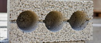
4. Masonry of building and special bricks, clinker, ceramics, terracotta, artificial and natural stones of any shape, etc.
1. (Deleted, Amendment No. 1).
2. To clarify the type of material, in particular, materials with the same type of designation, the graphic designation should be accompanied by an explanatory inscription in the drawing field.
3. In special construction design drawings for the reinforcement of reinforced concrete structures, designations according to GOST 21.501 should be used.
4. The designation of the material on the view (facade) is allowed not to be applied completely, but only in small areas along the contour or spots inside the contour.
5. Oblique parallel hatching lines should be drawn at an angle of 45 ° to the contour line of the image (Fig. 2 a) or to its axis (Fig. 2b), or to the lines of the drawing frame (Fig. 2).
If the hatch lines attached to the lines of the drawing frame at an angle of 45° coincide in direction with the contour lines or center lines, then instead of an angle of 45°, an angle of 30° or 60° should be taken (Fig. 3 and 4).
Hatch lines should be drawn with an inclination to the left or right, but as a rule, in the same direction on all sections belonging to the same part, regardless of the number of sheets on which these sections are located.
(Changed edition, Amendment No. 1).
6. The distance between parallel straight hatching lines (frequency) should, as a rule, be the same for all sections of a given part performed on the same scale and is selected depending on the hatching area and the need to diversify the hatching of adjacent sections. The specified distance should be from 1 to 10 mm, depending on the hatching area and the need to diversify the hatching of adjacent sections.
(Changed edition, Amendment No. 2).
7. Narrow and long cross-sectional areas (for example, stamped, rolled and other similar parts), the width of which in the drawing is from 2 to 4 mm, may be completely hatched only at the ends and at the contours of the holes, and the remaining cross-sectional area - in small sections in several places (Fig. 5 and 6). Glass hatch lines (Fig. 7) should be drawn with an inclination of 15-20 ° to the line of the larger side of the section contour.
8. Narrow cross-sectional areas, the width of which in the drawing is less than 2 mm, may be shown blackened, leaving gaps between adjacent sections of at least 0.8 mm (drawings 8, 9).
In construction drawings, it is allowed to designate any material as metal on sections of a small area or not to use the designation at all, making an explanatory inscription in the drawing field.
9. Designation specified in paragraph 3 of table. 1, and the designation of the backfill in the cross-section is done by hand.
(Changed edition, Amendment No. 1).
10. For adjacent sections of two parts, you should take the slope of the hatching lines for one section to the right, for the other - to the left (counter hatching).
When shading “in a cage” for adjacent sections of two parts, the distance between the hatch lines in each section should be different.
In adjacent sections with hatching of the same slope and direction, you should change the distance between the hatching lines (Fig. 10) or shift these lines in one section relative to another, without changing the angle of their inclination (Fig. 11).
Hatching of aerated concrete GOST
3. Expanded steel
4. Masonry of building and special bricks, clinker, ceramics, terracotta, artificial and natural stones of any shape, etc.
1. (Deleted, Amendment No. 1).
2. To clarify the type of material, in particular, materials with the same type of designation, the graphic designation should be accompanied by an explanatory inscription in the drawing field.
3. In special construction design drawings for the reinforcement of reinforced concrete structures, designations according to GOST 21.501 should be used.
4. The designation of the material on the view (facade) is allowed not to be applied completely, but only in small areas along the contour or spots inside the contour.
5. Oblique parallel hatching lines should be drawn at an angle of 45 ° to the contour line of the image (Fig. 2 a) or to its axis (Fig. 2b), or to the lines of the drawing frame (Fig. 2).
If the hatch lines attached to the lines of the drawing frame at an angle of 45° coincide in direction with the contour lines or center lines, then instead of an angle of 45°, an angle of 30° or 60° should be taken (Fig. 3 and 4).
What is shading on a plane?
For easy reading of the technical drawing information, parts are indicated in sections. They display what exactly is in the cutting plane of the product, so that the elements are easily and simply distinguished and recognized for all areas of construction. Hatching of reinforced concrete and its parts is carried out with an inclined sand-gravel landscape 0.3 mm thick. For metallic materials, lines are drawn at equal distances. Non-reinforced concrete is indicated in the diagram as a sand-gravel pattern. Narrowed areas are shown blackened. The symbol for concrete in the drawings is strokes that are made intermittently and at an angle. Parallel lines are drawn of the same type and scale from 1 to 10 mm.
To depict such material on paper, it is customary to use a sand-gravel landscape tilted at a certain angle.
shading of bricks on GOST drawings
Tree designation in the drawing
In the Technique section, the question How to hatch metal, pressed material and wood in drawing? asked by the author Alexander B, the best answer is HATCHING. On the drawing, sections are highlighted with hatching. Its type depends on the graphic designation of the material of the part and must comply with GOST 2.306 - 68 * (Fig. 9.1). Metals and hard alloys in sections are indicated by inclined parallel hatching lines drawn at an angle of 45 degrees to the contour line of the image or to its axis, or to drawing frame lines (Fig. 9.1). If the hatch lines drawn to the drawing frame lines at an angle of 45 degrees coincide in direction with the contour lines or center lines, then instead of an angle of 45 degrees, an angle of 30 or 60 degrees should be taken (Fig. 9.1).Hatching lines should be drawn with an inclination to the left or right, but as a rule, in the same direction on all sections belonging to the same part, regardless of the number of sheets on which these sections are located. Distance between parallel lines hatching lines (frequency) should, as a rule, be the same for all sections of a given part performed on the same scale. The specified distance should be from 1 to 10 mm, depending on the hatching area and the need to diversify the hatching of adjacent sections. Narrow and long cross-sectional areas (for example, stamped parts), the width of which in the drawing is from 2 to 4 mm, are recommended to be completely hatched only on ends and at the contours of the holes, and the remaining cross-sectional area - in small sections in several places (Fig. 9.1). Narrow cross-sectional areas, the width of which in the drawing is less than 2 mm, may be shown blackened, leaving gaps between adjacent sections of at least 0.8 mm (Fig. 9.1). For adjacent sections of two parts, you should take the slope of the hatching lines for one section to the right, for the other - to the left (counter hatching). When shading “in a cage” for adjacent sections of two parts, the distance between the hatching lines in each sections should be different. In adjacent sections with hatching of the same slope and direction, you should change the distance between the hatching lines (Fig. 9.1) or shift these lines in one section relative to the other without changing the angle of their inclination.
Answer from 2 replies[guru]
Hello! Here is a selection of topics with answers to your question: How to shade metal, pressed material and wood in drawing?
Answer from 2 replies[guru]
Hello! Here are more topics with the answers you need:
Answer the question:
22oa.ru
As indicated in the drawings: design features
Graphically designate drawing sections for different types of materials so that the builder understands what material the component part or product was made from. According to GOST, lines in an official drawing document must be drawn at an angle of 45 and 90° to the axis and frame of the entire drawing. Shade parts of structures and their parts in one direction for a specific product. If the hatching line coincides with the contour, then change the angle of their execution - 30-60°. Sectional figures give a general idea of what the elements are made of, and therefore additionally describe the material itself. The full characteristics are written in the specifications under the drawing or statements.
The correct angle of graphic filling of the material section should be equal to 45 degrees relative to the axis and frame of the entire drawing.
In addition to the basic requirements, it is worth considering:
- The frequency of the lines of the main element. If it coincides with another, additional explanation must be given depending on the location.
- For reinforced concrete parts of the structure, there is a separate type of design documentation GOST 21.107-78 “Conventional images of elements of buildings and structures.”
- The lines are drawn strictly to the left or to the right.
- Hatching of concrete is done by hand (except for strips with a straight direction).
- In a cage (insulation), intersecting sections of 2 parts are schematically depicted, which need to be drawn at a distance and these lines must be made different.
- It is necessary to use construction shading for construction and structural drawings of buildings with reconstruction or at the construction stage.
- Narrow cuts (from 2 to 4 mm) are partially painted over, along the edges in convenient places for perception.
- The material of the façade is depicted in small sections along the contour of the part.
Explanation of the basics of the regulatory document GOST 21.107-78
The standard has been cancelled, but shading is still used. The main conclusions regarding reinforced concrete products are as follows:
- prestressed reinforced concrete is depicted in 2 straight lines, the next with a dotted line;
- concrete with reinforcement is displayed in alternately drawn lines, broken and continuous;
- unreinforced is hatched dotted.
Each type of material is depicted in a specific way.
This means that in a monolithic slab on a large scale in the drawing, the section with the arrangement of reinforcing elements (schematically done in circles) and concrete without reinforcement is shaded as concrete. In the cross-section of the entire building, the reinforcement component on the slab section is not shown, being performed as a reinforced concrete part (solid and dotted alternately). It is not customary to shade metal, that is, the place where the reinforcement of parts is shown is not shaded. Designation lines and reinforcement cannot be done in the same type, since when reading the document, the shading is difficult to make out.
GOST 2.306-68 Designations of graphic materials and rules for their application on drawings
Designations of graphic materials in sections
Designations of graphic materials in views
Rules for applying shading in drawings
Graphic designation of the material in sections and in views is shading performed with thin solid lines. The shape of the hatching in accordance with GOST 2.306-68 gives an idea of the material from which the part is made.
Graphic designation of materials in sections, depending on the type of materials, must correspond to those given in table. 1.
| Material | Designation |
| 1. Metals and hard alloys (The general graphic designation of materials in sections, regardless of the type of material, must correspond) | |
| 2. Non-metallic materials, including fibrous monolithic and slab (pressed), with the exception of those indicated below | |
| 3. Wood | |
| 4. Natural stone | |
| 5. Ceramics and silicate materials for masonry | |
| 6. Concrete | |
| 7. Glass and other translucent materials | |
| 8. Liquids | |
| 9. Natural soil |
- Composite materials containing metals and non-metallic materials are referred to as metals.
- The graphic designation of paragraph 3 should be used when there is no need to indicate the direction of the fibers.
- The graphic designation of paragraph 5 should be used to designate brick products (fired and unfired), refractories, building ceramics, electrical porcelain, slag concrete blocks, etc.
When highlighting materials and products on a view (facade), their graphic designations must correspond to those indicated in the table. 2.
| Material | Designation |
| 1. Metals | |
| 2. Corrugated steel | |
| 3. Expanded steel | |
| 4. Masonry of building and special bricks, clinker, ceramics, terracotta, artificial and natural stones of any shape, etc. | |
| 5. Glass |
- To clarify the type of material, in particular, materials with the same type of designation, the graphic designation should be accompanied by an explanatory inscription in the drawing field.
- In special construction design drawings for the reinforcement of reinforced concrete structures, designations in accordance with GOST 21.107-78 should be used.
- The designation of materials on the view (facade) is allowed to be applied not completely, but only in small areas along the contour or spots inside the contour.
Install the following designation of the mesh and backfill from any material (in cross-section), indicated in Table 3.
| Material | Designation |
| 1. Grid | |
| 2. Backfill |
Oblique parallel hatch lines should be drawn at an angle of 45 o to the image contour line (Fig. 1) or to its axis (Fig. 2) or to the drawing frame lines (Fig. 3)
| Figure 1. Hatching at an angle of 45 0 to the contour line | Figure 2. Hatching at an angle of 45 0 to the axis If the hatch lines, brought to the line of the drawing frame at an angle of 45 o, coincide with the contour lines or center lines, then instead of an angle of 45 o, an angle of 30 o or 60 o should be taken (Fig. 4 and 5). Hatch lines should be drawn slanted to the left or right, but, as a rule, in the same direction on all sections belonging to the same part, regardless of the number of sheets on which these sections are located. The distance between parallel straight hatching lines (frequency) should, as a rule, be the same for all sections of a given part performed on the same scale and is selected depending on the hatching area and the need to diversify the hatching of adjacent sections. The specified distance should be from 1 to 10 mm, depending on the hatching area and the need to diversify the hatching of adjacent sections. |
Narrow and long cross-sectional areas (for example, stamped, rolled and other similar parts), the width of which in the drawing is from 2 to 4 mm, are recommended to be completely hatched only at the ends and at the contours of the holes, and the remaining cross-sectional area - in small sections in several places (Fig. 6 and 7). In these cases, the glass hatch lines (Fig. 8) should be drawn with an inclination of 15 - 20 o to the lines of the larger side of the section contour.
Narrow cross-sectional areas, the width of which in the drawing is less than 2 mm, may be shown blackened, leaving gaps between adjacent sections of at least 0.8 mm (Fig. 9, 10).
In construction drawings, it is allowed to designate any material as metal on sections of a small area or not to use the designation at all, making explanatory notes in the drawing field.
The designation specified in paragraph 3 of the table. 1, and the designation of the backfill in the sections is done by hand.
| Figure 9. Hatching of narrow areas whose width in the drawing is less than 2 mm. | Figure 10. Hatching of narrow areas whose width in the drawing is less than 2 mm. |
For adjacent sections of two parts, you should take the slope of the hatching lines for one section to the right, for the other - to the left (counter hatching).
When hatching in a checkerboard for adjacent sections of two parts, the distance between the hatching lines in each section should be different.
In adjacent sections with hatching of the same slope and direction, you should change the distance between the hatching lines (Fig. 11) or shift these lines in one section relative to the other without changing the angle of their inclination (Fig. 12).
Figure 11. Sample of hatching of adjacent areas
Figure 12. Sample of hatching of adjacent areas
Figure 13. Sample of hatching of large areas
Standards for developers and manufacturers
Before the advent of GOST 2.306-68, the current drawing standards were GOST 3455-59 and GOST 11633-65, but, in fact, they were duplicates of each other. Sources of regulatory documentation for the correct design of drawings:
- Image of drawing fonts. — GOST 3454–59.
- Drawing lines - GOST 3456–59.
- Hatching of elements of various structures in sections - GOST 3455–59.
- Conventional graphic images of building elements and materials - GOST 2.306-68.
- Dimensions in the drawing diagram - GOST 3458–59.
To correctly execute the drawing, you must use the symbols specified in the regulatory documentation.
It should be noted that shading of concrete and concrete connections with steel reinforcement in a specially developed computer drawing design system in the AutoCAD program differs from hand-made drawings. They use a special fill of elements to fill the selected area according to an existing pattern.
The rules provided for by the basic requirements of the standards must be followed. In order to correctly apply and understand the indicated dimensions, you need to study the conventions that are established by GOST 2.307-68. It is worth considering that inscriptions with explanations are applied to the drawing if different types of concrete and structures made from it are used (precast, monolithic, prestressed, etc.). On construction drawings for concrete elements with a homogeneous component, panels, wall blocks and elements that do not need to identify the composition, designations are not used.
Question 3. How to add more hatching in AutoCAD?
When you need to continue working with hatching, you don’t have to re-enter the “Hatching” command as we did in the first question. You just need to select the hatch (click on it) and you will immediately be taken to the familiar ribbon for creating and editing hatches. There we are now interested in a button called “specify points”, click on it and yes, select other areas for shading. It's simple, look at the examples below and the captions for each picture.
The shading is highlighted.
Having entered the familiar feed, click on the “Specify points” button.
We indicate the areas that we forgot to shade and press the space bar.
Voila, we have shaded a new area in AutoCAD.
Let's look at the example of a tree. Unfortunately, AutoCAD does not have a tree hatch sample. Therefore, you should add it yourself; it is very easy to do.
Step 0.
Hatching concrete according to GOST standards
How is reinforced concrete shading done correctly in drawings? Are there any standards establishing the way of designing sections and types of building structures? We have to find answers to these and some related questions.
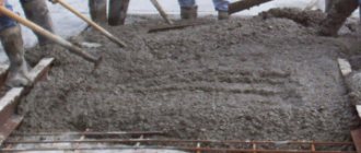
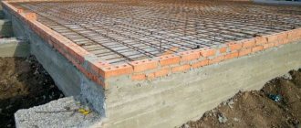
This is what concrete looks like in cross section. How is it indicated on the drawings?
Hatching concrete: material designations and GOST
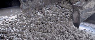
Hatching is a conventional symbolic designation of various building materials. As a rule, shading is used when working with concrete or reinforced concrete structures. The drawing is made using a pencil and consists of strokes, lines, and dots located at a certain distance or intersecting. Schemes are used in most construction work, but there are certain nuances when shading concrete.
Investigation
Like the reader, the author of the article was once a schoolchild and, among other things, attended drawing classes. Hatching of cuts was still in use then; I remember some designations especially well. Among them is a way to designate concrete, which required some artist’s skills: it should have been depicted as something like a landscape of a sand-gravel quarry, made by the hand of Ostap Bender (see also the article “Freezing temperature of concrete - important information for builders”).
As it turned out much later, the drawing teacher simply did not know about the new standard adopted after he received higher education and taught schoolchildren the same way he himself was taught.
GOST 3455 - 59
The standard came into force on January 1, 1959 and was canceled exactly 12 years later, on January 1, 1971. Its title is “Drawings in mechanical engineering. Hatching in sections and sections.”
Technical drawing
Hatching in sections and sections performed in the form of parallel straight lines drawn at an angle of 45° to the center line or contour line taken as the main one. The slope of the lines can be either left or right; but for all cuts and sections related to the same part, hatching should be done with the lines sloping in the same direction.Note: The thickness of the hatch lines is in accordance with GOST 3456-46.
When shading in sections and sections, the following conventions should be used:
For examples of the use and combination of symbols, see Fig. 45, 50, 51 and 52.
Notes.
1. The above symbols define this or that material only in general terms; all necessary data regarding materials must be placed in specifications, statements, etc.
2. Other materials can be indicated in sections and sections by hatching like “Metals” with an explanatory inscription directly next to the hatched surface (Fig. 51).
3. Metal gaskets and fills may be indicated in sections and sections, in addition to shading into the grid, also by shading according to the “Metals” type.
4. The following shading options are allowed:
In the same drawing, shading must be done either according to the indicated options, or according to the symbols of paragraph 2.
The symbols for wood and earth, as well as the circles for concrete, are done by hand. Glass can also be marked by hand.
The symbols for wood and earth, as well as the circles for concrete, are done by hand. Glass can also be marked by hand.
When two surfaces meet in a section, the slope of the hatching lines is taken for one surface to the right, for the other to the left - “counter hatching” (Fig. 45). For materials from the group “Plastic masses, leather, rubber, gaskets, packings, fillings”, in this case, shading of the “Metals” type with an explanatory inscription on the drawing can be used.
If two touching surfaces are at the same time adjacent to a third surface, then the hatching should be varied either by changing the distances between the hatching lines without changing the angle of inclination, which in all cases should remain equal to 45°, or by shifting the hatching lines of one surface relative to the other with the same distance between the hatching lines (Fig. 46 and 47).
Narrow areas of hatching, the width of which in the drawing is equal to or less than 2 mm, can be filled entirely if this does not affect the clarity of the drawing. Gaps should be left at the points of contact of the filled surfaces (Fig. 48 and 49).
In cases where you have to deal with large areas of shading of masonry or concrete mass, you should limit yourself to shading only at the contour (Fig. 50).
Hatching of the superimposed sections is performed with the usual inclination to the center line or to the contour line taken as the main one (Fig. 53). Hatching of extended sections is performed with the usual inclination (45°) to the section line (Fig. 54).
When depicting a section of a package of sheets of rotors, armatures, transformers, stators and chokes, shading like Fig. is allowed. 55.
General information
GOST shading of materials is a symbol. Using shading on the diagram, you can determine the type of building material. This is required for convenience during the construction of objects for various purposes.
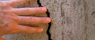
Concrete is shaded from several constituent elements that are located at some distance from each other, and the lines and strokes used may intersect.
Such drawings are used during the construction of many construction projects. However, there are some nuances that must be taken into account:
- you can additionally draw up the required number of drawings and indicate explanations for individual building materials that were not taken into account during the creation of the standard;
- taking into account GOST, the designation of concrete on the drawings may be absent if this is not necessary, or it may be partially indicated - to highlight a specific object.
Today, several established templates are used in construction: GOST 3455–59, GOST 2306−68, GOST R 21.1207−97.
Hatching of concrete on drawings (cement, expanded clay concrete, aerated concrete) - symbol
Hatching of concrete is a symbol for various materials in drawings in accordance with current GOSTs.
Thanks to the shading on any construction diagram, you can easily determine the type of building material without the need for additional documents and explanations. In this way, it is possible to significantly simplify the process of designing and constructing various types of objects.
Hatching concrete on drawings is an opportunity to unify the basic designations regarding materials, which will be understandable to any designer or builder. Concrete is shaded in a certain way (like all other materials), the type of designation depends on the presence/absence of reinforcement and other factors.
Designation according to GOST 3455–59
This established template was created in the 60s, it began to be used on construction diagrams from 02/01/1962. GOST was valid until 02/02/1973. It describes drawings for mechanical engineering. The conditional values were as follows:
- non-metallic building materials - marked in the form of lines inclined to the left or right at an intersection of 90 degrees;
- metal - marked with oblique lines, maintaining the same distance;
- liquids - vertical dotted lines with tapering intervals;
- rings and cracks - a longitudinal section was used for symbolic designation;
- wood - designations were used taking into account the characteristics of wood;
- solutions were marked with horizontal hatching, and the gaps were made narrow;
- plywood - sectional section;
- unreinforced reinforced concrete structures were made in the form of sand and gravel;
- expanded clay concrete - sand gravel was applied, additionally 3 crossed lines were used, which are located in different directions;
- glass - indicated on the diagrams using strokes of three varieties and different intervals;
- reinforced concrete - oblique strokes with a sand-gravel pattern;
- brickwork - two types of lines intersecting at an angle were used.
Difference GOST 2.306−68
As already indicated, the previous system was abolished in 1973. This standard has been modified by new designation elements.
The main difference between the new shading of reinforced concrete according to GOST is the mandatory compliance and rigor of the standard. This established template has been simplified. The new system did not have any special effects, everything was clear and precise. The main changes were as follows:
- stones - depicted in the diagram as an inclined dotted line;
- tree - designated using identical arcs located at the same distance;
- ground - three strokes were used, representing a group with small intervals;
- hatching of concrete according to GOST was done using dotted lines, observing a certain slope;
- ceramic building materials and silicate - were indicated by elements that consisted of several groups, and there was a significant distance between the lines.
New graphic elements make it possible to indicate on the drawings the required building materials during the construction of buildings and other structures. This is convenient both during the production of individual elements and during the creation of various objects.
The marks are drawn with thin lines, drawing them in the required order and at a given distance. Within one schematic drawing, symbols of metal products should stand out from other building materials. Therefore, more space must be left between the lines when specifying these elements.
Features of GOST from 1973
There are also other features of the standard. These rules are expressed in the following points:
- explanations must be provided;
- if there is a similarity in the drawing of various elements during which various materials are described, then one cannot do without auxiliary information;
- façade building materials are not indicated in full; in this case, it is only necessary to partially indicate the outline;
- features of shading of building material on the diagram are indicated in GOST 21 .107−78;
- There are no designations for reinforced concrete structures in the standard, so a special template was developed for them.
There are also certain rules that the 1973 standard provides for. Hatching of concrete is carried out in this way:
- Small sections are marked with strokes. This designation is similar to the description of a metal.
- Lines that need to be drawn at an angle must be drawn with a clear slope of 45 degrees. The angle must be determined taking into account the landmark not only of the diagram itself, but also in compliance with the contour of the image.
- In adjacent planes, lines must be drawn at different angles.
- Hatching is left-handed or right-handed, but in one design the angle for the sections should be the same.
- Long narrow cuts do not have to be completely shaded; shading can be only along the edges or in several areas that are chosen in any form. Sections with a thickness of no more than 3 mm are completely shaded.
The rules provided for by the standard must be complied with.
Geological hatching for AutoCAD 2009 - 2013
To add geological hatches to AutoCAD 2009 - 2013, download the desired hatch from the link below and add the downloaded file to the folder with AutoCAD installed \ Program Files\Autodesk\AutoCAD XXXX\Support
You will find the hatch data by opening the Hatch Pattern Palette on the Custom .
Ver. 1.0 — Samples of AutoCAD hatching according to GOST 21.302-96 Sedimentary soils alevro 1 Siltstone angidr 2 Anhydrite argill 3 Argillite brekch 4 Breccia valuny 5 Boulders galka 6 Pebbles gips 7 Gypsum glina 8 Clay gravel 9 Gravelite graviy 10 Gravel dolomit 11 Dolomite dr esva 12 Dresva izvest 13 Limestone il 14 Il k_sol 15 Rock salt kamni 17 Lump stones konglom 18 Conglomerate less 19 Loess mel 20 Chalk mergel 21 Marl opoka 22 Opoka radiolarite pesok_g 23 Gravelly sand pesok_k 24 Coarse sand pesok_m 25 Fine sand pesok_p 26 Silty sand pesok_s 27 Medium sand pesch 28 Sandstone pochva 29 Soil-vegetable sapropel 30 Sapropel sugl 31 Loam sugl_m 32 Loam moraine supes 33 Sandy loam supes_m 34 Sandy loam moraine torth 35 Peat trepel 36 Trepel (diatomite) tufit 37 Calcareous tufit scheben 38 Crushed stone Ver. 1.0 — Samples of AutoCAD hatching according to GOST 21.302-96 Artificial soils isk_2 2 Alluvial sandy ... isk_3 3 Igneous ... isk_4 4 Silty clay ... isk_5 5 Uncemented sand ... isk_6 6 Compacted in the natural state Ver. 1.0 — Samples of AutoCAD hatching according to GOST 21.302-96 Intrusive (deep) soils gab_dior 1 Gabbrodiorite granit 2 Granite gr_porf 3 Porphyry granite gr_dior 4 Granodiorite gr_sien 5 Granosyenite diorit 6 Diorite peridot 7 Peridotite sienit 8 Syenite Ver. 1.0-samples of the barns of auto cadets according to GOST 21.302-96 Effusive (excessed) soils Lava_k 1A Lava_O Lava 1b Lava Lava_S 1c Lava Lava_H 1g Lava Lava_r 1d lava of different compositions Pemza 2 pemes 2 pemes Tuf_k 3a tu. F sour composition TUF_O 3B Tuff of basic composition tuf_r 3v Tuff of different composition tuf_s 3g Tuff of intermediate composition tuf_h 3d Tuff of alkaline composition Ver. 1.0 — Samples of AutoCAD hatches according to GOST 21.302-96 Metamorphic soils amfibol 1 Amphibolite gneis_a 2a Gneiss gneis_b 2b Gneiss kvarcit 3 Quartzite milonit 4 Mylonite mramor 5 Marble rogovik 6 Hornfels jasper slanc_gl 7 Slate phyllite Additional types of hatches for system C REDO_GEO tehno Bulk namyv Alluvial pochv_r Soil-vegetative il_glin Clay silts il_sugl Loamy silts il_sups Sandy loam silts gl_e Eluvial clay gl_d Clay gl_l Band clay sugl_d Loam sugl_e Eluvial loam sugl_n Unclearly layered loam. sugl_l Banded loam sugl_dr Ancient loam supes_e Eluvial sandy loam supes_d Sandy loam supes_dr Ancient sandy loam gl_dr Ancient clay gr_gr Gravel soil dr_gr Sandy soil sch_gr Crushed stone gabbro Gabbroids piroxen Pyroxenite perid Peridotite diabaz Porphyrite diabase kvarc_p Quartz. porphyries tufy Tuffs tufoporf Tuff porphyrites gneis_c 2v Gneiss serp Serpentinites slanc_hl Chlorite schists slanc_kv Qu-chlor. slates ultra_k Ultra-acid Additional types of shadings developed for LenMetroGiproTrans sup_lmgt Sandy loam / LMGT sug_lmgt Loam / LMGT gl_lmgt Clays / LMGT gll_lmgt Belt clays / LMGT sgl_lmgt Loam. tape/LMGT gld_lmgt Clay disloc. /LMGT glk_lmgt Cambrian clay. /LMGT glp_lmgt Rubbed clay. /LMGT prq_lmgt Clays re-sedited./LMGT Additional types of hatches developed for SurgutNIPIneft ice Ice /SNIPIN torf_I Peat IB /SNIPIN torf_II Peat II /SNIPIN torf_III Peat III /SNIPIN Additional types of hatches developed for ZapURALTISIZ sugl_cht Sugl. quaternary (ZUTISIZ) sugl_neo Sugl. Neogene (ZUTISIZ) sugl_pro Sugl. subsidence (ZUTISIZ) gl_kor Indigenous clay (ZUTISIZ) gl_neo Neogene clay. (ZUTISIZ) gl_chtv Quaternary clay (ZUTISIZ) Additional types of shading developed for UralGiproTrans slnc_ugt Metamorphic shales. prf_ugt Porphyrites and tuffs
Latest innovations
The GOST of 1973 had a significant drawback: it did not have a standard for describing reinforced concrete. This explains the need to develop GOST R 21.1207−97. This flaw was corrected in the installed template and the necessary designation was added.
Most often, this standard is used when road work is carried out. In addition to asphalt, as well as other building materials, in this template a special place is given to the following points:
- reinforced concrete, which is equipped with stressed reinforcement - 2 solid lines are used alternately, followed by one dotted line;
- reinforced concrete - solid and broken lines are drawn in turn;
- The shading of concrete in the diagram is indicated by a dotted line.
The main task when using reinforced concrete shading is the need to show, with the help of design drawings, the structure that needs to be implemented. Conventions help greatly in accomplishing this task.
Today, two main established templates are considered valid; both GOST standards are used in the construction industry and mechanical engineering. These templates enable builders to quickly determine the required building materials during the construction of various structures.