To crush large pieces of rock after mining, crushing devices, simply called crushers, are used. Special mechanisms operate on the principle of impact, crushing, abrasion and splitting; in some devices, stones are crushed by breaking. For crushed stone, the crushing and splitting principle is used, since these types of equipment do not require large amounts of electricity.
When installed in a quarry, stationary crushing and screening equipment does not require design documentation or foundations; it can move under its own power at the work site . To transport it to another development, it is dismantled and loaded onto transport . Installation time before starting work takes about 1-2 days.
Purpose of crushers and their main characteristics
The destruction of the source material to fractions of a given size is the main and only task of crushing equipment. It is clear that the performance of grain grinders used in agriculture is not comparable to the same parameter of a cone crusher operating in a crushed stone production plant. And yet their main characteristics are the same, namely:
- the largest size of the object to be processed;
- unit performance;
- maximum hardness of the processed material;
- fraction size obtained at the output.
This list illustrates only the main characteristics. In reality, there are many more of them, the ability to adjust the output grain size and its range, for example.
Popular crusher models
These devices are manufactured by different companies and have different characteristics, but their main distinguishing feature is the principle of operation and methods of their use. Below are some of the most popular types of shredders.
Crusher Molot – 400
The hammer crusher of the Molot - 400 series is designed for grinding dry materials. The Hammer 400 crusher is used in cooking (crushes sugar, spices, caramel), agriculture (grain, peas, rice), construction (slag, gypsum) and other industries.
Hammer crusher Molot 400
Main advantages:
- convenient sieve change;
- low noise;
- low level of wear of parts.
Hammer feed crusher DKM - 5
The DKM-5 crusher is designed for grinding feed and mineral additives.
Widely used in agriculture to supply livestock farms. The device can operate in three modes: automatic, manual and adjustment.
Advantages:
- simple design;
- easy installation;
- long service life;
- low energy consumption.
Wood waste shredder
The principle of operation is to grind wood waste. It is very popular in the sawmill and logging industry. Suitable for wood chips, wood, as well as branches, large twigs, etc. Allows the production of various materials: shavings, sawdust, wood dust. Used to avoid costs associated with the disposal of wood waste. In addition, the finished product can be used for further sale.
Multifunctional shredder (crusher) of wood waste and recyclable materials DU-2
The operating principle of the wood shredder and the functioning of the device are based on the principle of shredding wood waste, which takes place in several stages:
- purification of raw materials from foreign materials and transportation to the main production;
- grinding of raw materials;
- formation of the resulting product into fractions, removal of particles that do not correspond to general parameters;
- formation of finished products.
Hammer crusher (video)
Basics of classification
Crushers are classified according to their operating principle. By implementing its various variants, they find application in one or another sphere of human activity. In general, the types of crushers can be characterized by the following list:
- rotary crushers;
- with a roller working body;
- cone crushers;
- jaw type units;
- hammer crushers;
- centrifugal devices.
Typically, mobile crushing plants are included in a separate group. But these units belong to one of the listed categories. Their difference lies only in the presence of some type of chassis (car, trailer, crawler tracks are also possible). Let's take a closer look at each type.
Impact crushers
As the name suggests, the core of an impact crusher is a rotor rotating at high speed. Beats are mounted on it, from which the plastic bounces off. It hits the opposite reflective plates, which leads to its fragmentation. To obtain a finer fraction, a larger number of plates are installed to increase the number of collisions of plastic with them. Springs that give a certain degree of freedom to the reflective plates relative to the rotor allow particularly hard parts to slip into the gap without breaking to the required size. The units can be either single or double rotor. The latter implement a parallel or sequential processing algorithm. Some of the single-rotor ones can operate in reverse mode.
Roll crushers
Typically, such mechanisms are two- or single-roll. In the first case, crushing of the material occurs as it passes between the rolls. The second version of the roller crusher has only one roller that ensures the movement of plastic. Crushing occurs in the space between the roller and the grate. To obtain fine fractions, a unit of this type may contain three or more rolls.
The design of most roller crushers involves the presence of one rigidly fixed roller and a spring-loaded second one. By varying the spring stiffness, the required size of crushed material at the outlet is achieved. Its presence also prevents damage to the working parts when a large element hits, which the unit is not able to split.
The surface of the rolls can be smooth, textured or serrated, depending on the hardness of the material being processed.
DESIGNS OF CRUSHERS AND MILLS. DESCRIBE THEIR DEVICE AND PRINCIPLE OF OPERATION.
For coarse crushing, jaw and cone crushers are used, in which material with a piece size of no more than 1500 mm is crushed under the influence of mainly crushing and splitting forces to pieces measuring (300 - 100) mm.
Jaw crushers.
In a jaw crusher, material is crushed by crushing combined with splitting and bending between the fixed and movable jaws. The movable cheek approaches (during the power stroke) or moves away (during idle speed) from the fixed cheek when the eccentric shaft rotates. During the working stroke, crushing occurs, and during the idle stroke, the crushed material is discharged downwards under the influence of its own weight. The movement is transmitted to the cheek by a connecting rod, movably connected to an eccentric shaft, and two hinged spacer plates - front and rear. The rod and spring create tension in the moving system and promote idling of the moving cheek. By mutually moving the wedges, the width of the outlet opening and, consequently, the degree of grinding are adjusted.
Cone crushers
The material in cone crushers is crushed by crushing it when the surfaces of the internal moving and external fixed cones come together.
According to their purpose, cone crushers are divided into coarse, medium and fine crushers.
In a coarse crusher, a steep movable cone is driven around a fixed axis by an eccentric shaft using a bevel gear. The fixed cone (bowl) has its large base facing upward.
In a crusher for medium and fine crushing, a flat movable cone, mounted on a shaft rotating with the help of an eccentric glass, is located inside a stationary cone (facing the large base down).
After coarse crushing, the material is often further crushed in medium and fine crushers, in which the crushing is carried out from approximately 100 mm (the size of the largest pieces of the starting material) to 10 - 12 mm. For medium and fine crushing, roller, impact centrifugal and hollow cone crushers described above are used.
Roll crushers
The feed material enters a roll crusher, is pulled by a pair of smooth cylindrical rolls rotating towards each other into the gap between them and is crushed mainly by crushing. The rolls are placed on bearings in the housing, and the roll rotates in fixed bearings, and the roll rotates in sliding bearings, which are held in a given position (depending on the required gap width) using a spring. If a foreign object of excessive hardness enters the crusher, the movable roller moves away from the stationary one and the object falls out of the crusher (this eliminates the possibility of its breakage).
Impact centrifugal crushers:
Hammer crushers.
The hammer crusher consists of a body lined with steel plates. Discs are mounted on a rotating horizontal shaft, between which hammers are hinged. The material is crushed under the impact of rapidly rotating hammers. Crushing also occurs when pieces of material thrown by hammers strike slabs. Finally, the material is further reduced by impact, crushing and some abrasion on a grate, through which the crushed material is discharged as it falls downwards.
Reflective crushers.
From the material entering the deflector crusher for grinding, fines are sifted out on a grid, and the material enters the rotor, rotating at a peripheral speed of 12 - 70 m/sec. The rotor blades throw pieces of material onto hinged reflective shields.
In drum mills, the grinding of material occurs inside a hollow rotating drum using grinding bodies (balls, rods). The material placed in the mill is destroyed under the influence of impact and abrasive loads. Drum mills are classified according to the shape of the grinding media - ball, rod and self-grinding (without grinding media).
The mill drive consists of an electric motor, a gearbox and a gear drive. To reduce the starting torque, a friction clutch is provided in the drive circuit. When the mill is operating, the source material is fed into the drum through a hatch, crushed depending on the required grinding fineness for 5...8 hours, and then unloaded through the same hatch. To prevent grinding media from falling out of the mill when unloading the finished product, a tube with holes is inserted into the hatch.
For fine grinding, the most widely used are so-called ball mills (their design is similar to a rod mill), in which the product is processed by balls located with it in a hollow rotating drum. In ball mills, the grinding of material occurs under the influence of impacts of falling steel or silicon balls and by abrasion between the balls and the inner surface of the mill body.
The design of a rod mill is similar to that of a ball mill. To reduce the level of pulp (finely ground mixture) and increase the speed of passage of the crushed material, the diameter of the discharge neck of a rod mill is made significantly larger than that of a ball mill drum of the same diameter. The loading neck must easily pass a large amount of material, especially when the mill is operating in an open cycle at low degrees of grinding.
Vibrating mills The mill has a cylindrical or trough-shaped body, inside which a horizontal unbalanced shaft rotates on ball bearings from an electric motor (through an elastic coupling). The mill body is mounted on a foundation using massive valve springs and filled with grinding media, usually steel balls.
Jaw crushers
The design of these mechanisms requires the presence of two cheeks. One of them is mounted on a rigid base, and the other, fixed at the bottom to an axis, makes reciprocating turns on it. Frictional movements change the width of the gap between the cheeks, which leads to destruction of the material. Less common are specimens with both movable cheeks. In addition, the movable jaw in some units can perform not only a rotational movement relative to the axis, but also move this shaft up and down, which gives an ellipsoidal trajectory to the working surface and allows simultaneously with crushing to achieve a rubbing effect.
The material is fed into a cone-shaped space formed by the plates. Squeezing leads to crushing of the material, and during the return stroke, the crushed plastic falls into the expanding gap. If their size is still large, they will be compressed again by the next friction of the jaw crusher.
Cone crushers
The working unit, which crushes materials in the gap between the crushing cone and the bowl, which cyclically changes its size, is used in cone crushers. Structurally, the bowl is made as a rigidly fixed inverted cone. The working body moves back and forth inside it, changing the gap between the cones. The gap, constantly changing its width, is filled with the original material, which is crushed by a moving cone. The operating principle is similar to that of a jaw crusher, but has a significant advantage. The absence of idling significantly increases the productivity of the machine. Elements that cannot be crushed can fall into the gap due to the spring-loading of the fixed bowl suspension relative to the frame. Due to this, it can be shifted to the side or lowered within certain limits, thereby increasing the output gap.
The use of unbalanced vibrators as a drive for a moving cone makes it possible to obtain very fine fractions. In this case, the vibration of the entire apparatus is dampened by special unbalancers. This type of cone installation is called inertial.
Overview of designs and scope of crushers
Crushing is the process of mechanical destruction of solid raw materials (the broader term is disintegration). Solid minerals, building materials, chemical raw materials, abrasive materials, solid secondary raw materials, and some types of plant materials are subjected to crushing. Among all types of raw materials that undergo crushing, ores of ferrous and non-ferrous metals and non-metallic minerals (coal, granites, limestones) dominate. Every year, 2.5–3 billion tons of minerals are crushed worldwide [1–4].
Crushing at beneficiation plants is a preparatory process, as its goal is to prepare the source material for further crushing and enrichment.
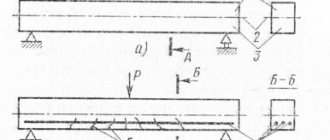
When crushing, pieces of minerals can be destroyed by compression, tension, bending and shear when the stresses arising in the material exceed the tensile strength limit. The main methods of material destruction are shown in Fig. 1.
Rice. 1. The main methods of material destruction: a - crushing; b - splitting; c - fracture; g - abrasion; d - blow
Crushing operations, as a rule, are used in conjunction with the processes of classification by size (screening) of solid raw materials. Screening is a technological process of separating solid particles into size classes, as well as separating the solid phase from the liquid phase by sifting through a moving or stationary sieving surface.
Crushing operations, like other disintegration methods, are used mainly to solve the following problems:
- To consistently reduce the size of minerals to sizes of 3–15 mm.
- To obtain raw materials of the size required by direct consumers for further processing.
- For the preparation of solid industrial and household waste for operations of their deep processing into secondary products.
The crushing process is carried out using special machines - crushers. Crusher (a. breaker, crusher; n. Brecher, Quetsche; f. broyeur, сoncasseur; i. trituradora, machadora, quebradora) is a machine for crushing mineral raw materials and other solid materials (Fig. 2). According to the design of the working body, they are distinguished: jaw crushers (crushing using two rectangular jaw plates, one or both of which perform an oscillatory movement); cone crushers (crushing inside the space formed by the inner surface of a stationary cone and the outer surface of a movable one undergoing gyratory movement); roller crushers (crushing between cylindrical rolls or a roll and a plate); impact crushers - rotary crushers, hammer crushers (crushing with bits or hammers attached to the body of a rapidly rotating rotor). Below we present an overview of some types of crushers available on the market of mining machines and equipment [5–11].
Rice. 2. General view of HJ series jaw crusher
Jaw crushers are distinguished by three main characteristics: by the location of the suspension axis of the movable jaw - with an upper or lower suspension axis; according to the nature of the movement of the movable cheek - with simple swing and with complex (rocking movement is combined with longitudinal along the surface of the cheek); according to the design of the driving mechanism - connecting rod-lever or cam.
Crushers of the HJ series have high productivity, and the energy intensity of the destruction process and power consumption are quite low.
Peculiarities. Increased productivity by optimizing the movement of the movable jaw and cavity of the machine. The counterweight weight and structure of the jaw crusher are adjusted, and the vibration of the whole machine is greatly improved.
Application area. It is used at mining enterprises in the Russian Federation and CIS countries in the processing of various materials in the mining and construction industries, for crushing granite, marble, basalt, limestone, quartz, cobblestone, iron ore, copper ore and some other minerals and rocks. Technical characteristics of this type of crushers are presented in Table 1 [12–14].
Table 1
Specifications _
| Model | Loading window size (mm) | Max. Power size(mm) | Discharge window size (mm) | Productivity (t/h) | Power, kWt) | Overall dimensions, mm) |
| HJ98 | 650×980 | 560 | 75–175 | 110–350 | 90–110 | 2470×2000×2180 |
| HJ110 | 800×1100 | 660 | 100–200 | 215–510 | 110–132 | 2875×2472×2530 |
| HJ125 | 950×1250 | 800 | 125–225 | 280–650 | 132–160 | 3320×2600×3120 |
Rice. 3. General view of HPC cone crusher
The Chinese HPC cone crusher has high crushing efficiency due to its optimized hydraulic control system. Used for secondary crushing in various technological lines for processing rocks and minerals.
Peculiarities. High degree of crushing, low operating costs, optimal forms of the finished fraction (end product), reduced downtime due to the use of hydraulic protection.
Application area. In the cement, mining, construction, metallurgical and other industries, as well as in the construction of roads and bridges, railways. Materials such as iron ore, granite, limestone, quartzite, sandstone, pavers and others. Technical characteristics of this type of crushers are presented in Table 2 [7–8].
table 2
Specifications
| Model | Cone diameter (mm) | Crushing chamber | Discharge slot width (mm) | Feeding material size(mm) | Productivity (t/h) | Power, kWt) | Overall dimensions, mm) |
| HPC220 | 1220 | Large | 19 | 210 | 185–300 | 220 | 2726×1950×2182 |
| Small | 13 | 105 | 150–210 | ||||
| HPC400 | 1570 | Large | 30 | 290 | 400–500 | 400 | 3447×2830×2977 |
| Small | 16 | 135 | 260–400 |
Rice. 4. General view of the hammer crusher 1 - rotor; 2 - body; 3, 4 — movable front and rear walls; 5 - loading part; 6 — adjusting device; 7 - lining
The developed hammer crusher is used to produce coarse powder with a size of 0–3mm. Crushing of the material occurs under the impact force of rapidly rotating parts: hammers, beaters. The crushing process also occurs under the influence of reflected impacts of discarded pieces of crushed material from fender parts installed inside the crusher body. The operating principle and general structure of a hammer (impact) crusher are as follows. The rotor rotates on a horizontal axis - the working part of the crusher, consisting of a shaft assembly with disks and hammers (beaters). Pieces of material entering the crusher are broken by the rotating impact parts of the rotor and thrown out of the crushing space.
Peculiarities. High productivity and high degree of grinding. Low energy consumption, homogeneous finished fraction.
Area of application. Crushers of this type are mainly intended for crushing rocks of various strengths, whose compressive strength is not higher than 320 MPa. For example, such as coal, salt, chalk, gypsum, limestone, glass, phosphates, etc. The technical characteristics of this type of crushers are presented in Table 3 [15–17].
Table 3
Specifications
| Model | Rotor diameter (mm) | Rotor Length(mm) | Hammer quantity | Feeding material size(mm) | Discharge gap adjustment range (mm) | Productivity (t/h) | Power, kWt) | Motor model | Circulation speed(rpm) | Overall dimensions, mm) |
| PC300×400 | 400 | 300 | 16 | <100 | <15 | 3–8 | 11 | 1100 | 855×795×862 | |
| PC400×600 | 600 | 400 | 20 | <150 | <15 | 8–15 | 18.5 | 1000 | 1155×1100×1255 | |
| PC600×800 | 800 | 600 | 28 | <220 | <20 | 15–30 | 45 | 900 | 2360×1500×1580 |
A brief overview of modern types of crushers is provided. From the analysis of extensive scientific, methodological and advertising material, it was established that the improvement of crushers should be aimed at increasing their unit power, service life, reducing noise and dust levels. Through the use of hydraulic systems to protect against breakdowns and regulate the size of crushed products, automatic systems for monitoring and controlling the operating mode of crushers.
Literature:
- Razumov K. A., Perov V. A. Design of processing plants. Textbook for universities. M., Nedra 1982. - 518 p.
- Donchenko A. S., Donchenko V. A. Handbook of concentrating plant mechanics. - M.: Nedra 1985.
- Design and operation of equipment for pelletizing factories. / Bessarab V.I.M.: Metallurgy 1986–152 p.
- Abramov A. A. Processing, enrichment and integrated use of solid minerals. T. 1. Enrichment processes and apparatus: Textbook for universities. - M.: Iz-vo MGGU, 2004. - 472 p.
- Hammer crusher // e341.ru URL: https://e341.ru/p53702691-molotkovaya-drobilka.html (access date: 10/30/2015).
- Velikanov V. S., Shabanov A. A. Application of a fuzzy approach to assess the influence of structure and control modes on the operational reliability indicators of mining machines and complexes // Mining industry. - 2013. - No. 3. - P. 101–102.
- HPC CONE CRUSHER // go-sst.ru URL: https://go-sst.ru/products/hpc-cone-crusher.html (access date: 10/30/2015).
- CRUSHING AND CRUSHERS // mtspb.com URL: https://mtspb.com/stati_i_dokladi/droblenie_drobilki.html (access date: 10/30/2015).
- Processes and machines for mineral processing / V. I. Karamzin, E. E. Sergo, A. P. Zhendrinsky and others. M., Nedra, 1974. - 560 p.
- Sergo E. E. Crushing, grinding and screening of minerals M., Nedra, 1985.
- Grishin I. A., Ismagilov K. V., Velikanov V. S. Electromechanical equipment of ore processing factories. Laboratory workshop. Magnitogorsk: Publishing house Magnitogorsk. state tech. University named after G. I. Nosova, 2020. - 68 p.
- g-ulanude.ru URL: https://g-ulanude.ru/ (access date: 10/30/2015).
- crushers-pro.net URL: https://crushers-pro.net/ (access date: 10/30/2015).
- https://orland.pro/poisk/gusenichnaya-mobilnaya-rotornaya-drobilka-zenith-pfw
- Velikanov V.S. Possibilities of the method of paired comparisons in establishing the significance of the indicators of mining machines and complexes according to the criterion of ergonomics // Vestnik KuzGTU. - 2013. - No. 4 - pp. 43–46.
- PFW rotary crusher (hydraulic) // zenith-crusher.ru URL: https://www.zenith-crusher.ru/products/crushing/hydraulic-impact-crusher.html (access date: 10/30/2015).
- Velikanov V.S. Methodology for assessing indicators of the economic effect of implementing measures to improve the level of ergonomic support for mining machines (using the example of quarry excavators) // Mine surveying and subsoil use. — 2014. — No. 3. — pp. 18–21.
Hammer crushers
The operating principle of a hammer crusher is based on the use of the impact effect produced by hammers mounted on a rotor rotating at high speed.
The primary mass fed into the receiving hopper or loading hole falls on hammers made of self-sharpening steel grades. The energy of fast-moving massive working bodies crushes it. The broken solid leaves the chamber due to its mass, waking up through the grates below. The internal space of the case is protected from destruction by a lining, most often made of the same steels as hammers.
The unit can have either one rotor or a larger number of them, carrying out either a parallel or sequential processing process. In this regard, the design of a hammer crusher is very similar to that of an impact crusher.
DESIGNS OF HAMMER CRUSHERS, THEIR TECHNICAL CHARACTERISTICS
Hammer crushers consist of the following components: a rotor with hinged hammers, grates, a housing and adjusting devices. The rotor is the main component of a hammer crusher. The design of the rotors is the same for all hammer crushers. The rotor is a disk mounted on a shaft, on which hammers are mounted using axes. The rotor shaft rotates on two bearings installed at its ends and is driven into rotation by means of a V-belt drive or an elastic coupling [11]. The number of rows of hammers is selected depending on the purpose of the crusher. The arrangement of hammers is characterized by the position of one row of hammers relative to the hammers of other rows. With a ring arrangement, the hammers of each row are placed one after the other along the circle of movement and, when rotating, form separate annular working zones (Fig. 7.7.2, a).
With a ring arrangement of hammers, their number in each row is usually the same. However, when using a crusher with an incomplete load, some of the hammers in the rows are removed one after another, with all the even-numbered hammers in one row being removed, and all the odd-numbered hammers in the adjacent row. This arrangement is called chess (Fig. 7.7.2, b). Overlapping hammer arrangements are achieved as a result of different designs of rotors and hammers. The most common are rotors in which the distance between the disks is greater than the thickness of the hammer and the hammers, using spacer bushings, are shifted in one row to one side of the disks, in the other - to the other side (Fig. 7.7.2, d). Hammers in these designs are used with a thickened head, which partially or completely covers the space above the rotor disks. The arrangement of hammers with overlap (Fig. 7.7.2, e) is typical for rotors with shaped disks, which are installed on the rotor shaft with an offset from one another to a certain angle. Each row of hammers is suspended in the cutouts of other disks. Thus, the hammers of one row are offset relative to the hammers of the adjacent row by half their thickness. In rotors of this design, the hammer oscillation angle is limited by a cutout in the rotor disk. Discs with niches (Fig. 7.7.2) are used for rotors of large crushers. Operating conditions of hammers are characterized by high dynamic load, abrasive wear and the need for frequent replacement. This creates special requirements for their design. Hammers shown in Fig. 7.7.3 a, b, are made in the form of a plate with four working surfaces. Such hammers have two holes for suspension on an axis. At each hole, two working surfaces can be used. When one surface wears out, the hammers are rearranged.
Hammers with two working surfaces (Fig. 7.7.3, c, d) are used for medium and coarse crushing. These are weighted hammers with a thickened head that provide a large supply of kinetic energy. U-shaped hammers (Fig. 7.7.3, e) have two working surfaces and are used for fine crushing. Hammers in the form of a ring (Fig. 7.7.3, e) have a serrated outer surface. Hammers with a limited oscillation angle are shown in Fig. 7.7.3, g, h. Vibration limiters are stops installed on the rotor in front of each hammer. When the rotor rotates, the hammers are pressed against the stops under the influence of centrifugal force and are in the working position. Upon impact, the hammer deflection angle is only a few degrees. After impact, the hammer returns to its working position. The hammer shown in Fig. 7.7.3, and can be pulled out as it wears out. To do this, the stop that holds the hammer is moved to a new place, and the hammer, turning, takes a new working position. The working surface of the hammer is designed so that, in any position, the part of the working surface in contact with the material is always at the same angle. In Fig. 7.7.3, k shows the composite structure of the hammer - the head (wearing part) and its holder. Such designs are typical for foreign companies (USA, Germany) that produce hammer crushers. Composite hammers are more complex in design and require more precise manufacturing, which increases their cost. The grates of hammer crushers are designed for the final formation of the grain composition of the crushed product. They perform the functions of both sorting and crushing organs. Stacked grates consist of individual grates made in the form of bars of rectangular, triangular or trapezoidal cross-section. The grate bars are inserted into special grooves in the grate frame and secured in it. The size of the gap between the grates is set using gaskets. Slotted plates are a cast plate with a cylindrical working surface with through holes. The fastening of the plates is bolted. Adjustable grates allow you to change the gap between them and the circle of rotation of the hammers. Adjustable gratings are made of several parts. Each part is separately attached to the crusher body, and it has its own devices for adjusting the gap, which are installed at one or two ends of the gratings. Adjusting devices are made in the form of eccentric bushings, screw or lever mechanisms. Closed grates (completely block the discharge opening) are used when it is necessary to obtain a crushed product of stable size. Open grates do not completely cover the discharge opening. The hammer crusher body supports all assemblies and is a welded or cast box-shaped structure. There are two main parts in the crusher body: the lower one - the frame with a built-in grate and consoles for bearings, and the upper one - with the receiving hole and the crushing chamber. The design of the upper part of the housing depends on the supply pattern of the source material to the rotor (Fig. 7.7.4): at an angle to the rotor in sector I; from above the rotor into sectors I—II or into sector II; at an angle onto the rotor in sector II.
Single-rotor crushers. One of the most common types of hammer crushers are single-rotor hammer crushers, which are the simplest in design and universal in application. Technical characteristics of domestically produced hammer crushers are given in table. 7.7.1.
A typical representative of single-rotor hammer crushers operating according to scheme 7.7.4, and also carrying out crushing in a closed cycle, is the SMD-112 crusher. Its design is shown in Fig. 7.7.5.
The crusher body is of welded sheet metal construction and consists of a frame and an upper part. On the side walls of the frame there are supports for installing rotor bearing housings, and there are also holes for installing and fastening the eccentric adjustment mechanism. The upper part of the body is made together with a receiving funnel, in which a metal curtain is mounted, which serves to prevent accidental ejection of pieces of material from the crushing chamber. Crushing plates are fixedly fixed in the upper part of the housing, forming a crushing chamber together with the rotor. The side walls of the crusher body are lined with wear-resistant plates. The rotor can be assembled with a two-, three- or six-row arrangement of hammers. The number of hammers in a row is odd. The grate is a closed type and consists of two prefabricated sections. The grates are suspended in the crusher body on axles mounted in eccentric rings. The lower end of the grates rests freely on the supporting axis. By turning the eccentric rings, the grates are brought closer to the circle of rotation of the hammers or away from it. The gap adjustment range is 30 mm.
Hammer crusher with top feed of source material, made according to Fig. 7.7.4, b, is shown in Fig. 7.7.6. The source material is crushed both by a free blow in the upper zone of the rotor and on the deflector plate and impact beam. The chipped particles enter the grates and, when they reach a given size, are removed from the crusher. The upper part of the housing has a receiving hole and forms a crushing chamber. In the crushing chamber, a reflective plate is installed vertically, which absorbs the impacts of stones thrown by hammers. The crusher rotor consists of a shaft with disks mounted on it, on which the axes of the hammers are fixed. The hammers are suspended on the axes in a checkerboard pattern and arranged in six rows: three rows of 11 hammers and three rows of 12. The rotor shaft is mounted on spherical double-row roller bearings. The crusher body provides the possibility of installing a rotor in right and left versions.
The grate is an open type and consists of two parts. The first grate in the direction of movement of the material is the suspended grate - its upper part is suspended on an axis, and its lower part rests on the adjusting bolts. The second grate - roll-out - is equipped with support rollers, along which it is rolled out of the crusher along special guides using the LRN-500 winch, supplied complete with the crusher. The guides are connected to an adjustment mechanism that serves to change the gap between the roll-out grate and the circle of rotation of the hammers. The deflector plate, breaker bar and grate form a single crushing and screening surface with four-way adjustable clearance to maintain a high crushing rate as the hammers wear out.
Feeding the source material through the center of the rotor is used in reversible crushers. An example is the design of a reversible crusher mod. NVK (Fig. 7.7.7) made in Germany. The crusher body is welded and box-shaped and consists of a frame 2, two end walls 6 and two side walls 8. The side walls of the housing in the crushing chamber are lined with wear-resistant plates. The end walls of the crusher body are hinged 4 to the crusher frame and, with the help of hydraulic cylinders, can open the crushing chamber, which greatly facilitates the repair and maintenance of the crusher. Hydraulic cylinders located under the consoles for fastening the bearings act on the end walls through the crank mechanism /. In the upper part of the body, massive impact plates 9 are hinged to both end walls, resting with their lower part on a spring-loaded rod 5, which serves to regulate the gap between the impact plate and the circle of rotation of the hammers 7 [11]. Technical characteristics of hammer crushers produced by foreign companies are given in table. 7.7.2.
Double rotor crushers. Double-rotor hammer crushers come in single-stage and two-stage crushing types. The general view of the SMD-114 double-rotor hammer crusher is shown in Fig. 7.7.8. The crusher consists of a body with a frame 3 and an upper part 2, a rotor 1 with hinged hammers, grates 4 and fender bars. At the top of the housing there are intake holes located above each rotor. A loading pipe with a transfer gate is mounted above the inlet openings.
The design of the crusher provides for the supply of material alternately to one or the other rotor or to both rotors simultaneously, i.e. according to two- or single-stage crushing schemes. Each rotor is equipped with six rows of hammers installed with overlap, i.e. the hammers of the next row cover the gaps between the hammers of the previous one. The rotation of the rotors is reversible, carried out by two individual electric motors through a V-belt drive. Grate bars consist of two parts connected by an intermediate hinge. The articulation of the grate grids and screw adjustment devices make it possible to change the gap between the grate bars and the circle of rotation of the hammers, both in size and shape. The screening surface of the grates is formed by slotted plates. Breaker bars serve to separate the crushing chambers, as well as to create a certain direction for the flow of crushed material when transferring it from one rotor to another. As the bars wear out, their position is adjusted by installing spacers under the supporting part.
- Previous: HAMMER CRUSHERS
- Next: MAIN PARAMETERS OF HAMMER CRUSHERS
DESIGN AND TECHNICAL CHARACTERISTICS OF CRUSHERS
The schematic design diagram of an impact crusher is shown in Fig. 7.6.2. The given geometric parameters of the diagram characterize the dimensions and relative position of the working parts of the crusher.… Read more
DETERMINATION OF THE MAIN PARAMETERS AND PERFORMANCE OF COARSE CONE CRUSHERS (KKD AND KRD)
Capture angle. The gripping angle of coarse cone crushers is the angle between the generatrices of the inner surface of the outer fixed conical bowl and the outer surface of the movable crushing... Read more
Centrifugal crusher
If we are talking about obtaining a very fine fraction with a high degree of homogeneity, then a centrifugal crusher is used. The principle of its operation is based on accelerating parts of the source material to high speeds. Under the influence of centrifugal force, they crash into the lining elements, breaking up in the process. This is how the centrifugal impact crushing method is implemented.
The large fraction is fed to the center of the accelerator cone and, sliding along it, is distributed between its blades, which have grooves. During movement along the latter, a high speed is acquired, which, upon collision with the lining, ensures fragmentation of the fraction. The channels of the lining itself are designed in such a way that the destructive effect is maximum.
Application of CD. (Figure 1).
There are three types of CD: for large CD, medium CD and small CD crushing. FCCs are used for crushing lump material with dimensions from 400 to 1200 mm, producing pieces from 75 to 300 mm.
KSD are used for crushing pieces from 60 to 300mm, producing material from 12 to 60mm. KMD are used for crushing pieces from 35 to 100 mm to obtain material from 3 to 15 mm. In production lines for producing crushed stone for road construction, mainly KSD and KMD crushers are used.
These units are used in road construction to crush pieces obtained from jaw crushers.
The method of crushing lump material in CD is based on the processes of crushing and bending the material between a fixed outer and internal movable crushing cone. The inner cone is mounted on a vertical shaft and, when the shaft rotates, its surface points move along an eccentric closed curve in relation to the outer cone. Unlike cyclically operating jaw crushers, in CD crushers the crushing process occurs continuously, with a constant loading of material.
Application of crushers
It is clear that the scope of application of certain units is determined by their capabilities. Roller crushers, for example, are optimal for grinding slag, construction waste and industrial waste. This implies the need for them at construction enterprises, various types of production, up to housing and communal services. No one prohibits their use in the mining or processing industries, if they correspond to the task.
The use of cone crushers, on the contrary, is limited by their purpose and characteristics. They allow you to obtain only large and medium fractions. To produce fine and uniform grinding, a centrifugal crusher is needed.
The design of the hammer crusher allows it to be used to produce recycled plastic. It will be useful at modern chemical enterprises and not only at them.
Simply put, there are enough models of crushing equipment that differ in productivity, degree of grinding and other parameters. You just need to choose the required, most suitable, from the point of view of economic feasibility.
It remains to be noted that the types of equipment considered can be made mobile. Mobile crushing plants are used in the mining, construction industries, crushing plastics and many other areas, and therefore are in great demand.
Calculation of the main parameters of jaw crushers
Parameters of crushers with simple jaw swing
An analysis of the size characteristics of crushed ore shows that the loading cavity with a filling degree of ψ = 0.3 - 0.6 contains ores of the following size:
- 0.8-0.85 V (B is the width of the loading slot) - 4-6% of the volume being filled;
- 0.4-0.5 V - 11-15% of the filled volume;
- 0.15-0.3 V - 70-85% of the filled volume.
In this case, it is convenient to select crusher parameters using L.S.’s method. Kokhan to represent the filling of the loading cavity with a conditionally spherical loading so that the relation is satisfied
With this choice of load, the size of the resulting pieces at a filling degree of ψ = 0.59 - 0.595 will be:
- (0.8-0.85) V - 6%;
- (0.43-0.5) V - 11.6%;
- up to 0.3 V - 84%.
A comparison of the given and obtained results shows that, in quantitative terms, the choice of ball loading gives satisfactory results.
Using the previous dependence, we determine the denominator of the progression:
Below are the design parameters (including the nominal crushing ratio and progression denominator) for crushers of different sizes:
It is known that during coarse crushing, when the size of a piece of ore changes from Dz to a product of size dz, the work for its crushing is determined by the dependence
On the other hand, the work of the elastic force Pz on the path Sz = Dz -dz is calculated by the formula Az = PzSz/2. Equating the indicated dependencies, the crushing force of any Z-piece is calculated
and the total force over the entire loading cavity at the nominal size of the unloading gap is equal to the formula L.S. Kohana:
For average crushing, the work is proportional to the change in the surface of the pieces, and in this case the total crushing force at the nominal value of the unloading gap is:
Using the formula obtained, the forces of crushers ShchKD4x6, Shch KD6x9, ShchKD9x12 were calculated. For comparison, the experimental forces for crushing ore with strength σв = 200 MPa are shown above.
When changing the width of the unloading gap e in the range from en to emax, the crushing force is:
A study of the spherical loading model shows that the force along the cheek is distributed linearly and the center of pressure is located from the suspension point of the movable cheek at a distance LCT ≈ 0.44 of its length.
At each moment of time, the total force depends linearly on the size of the crushed bodies or in proportion to the angle of swing of the cheek a from the angle a l corresponding to its front position to the angle a k corresponding to the rear final position. Taking the angles a of the eccentric shaft from the vertical in a counterclockwise direction, the current values of the crushing force are determined from the kinematics of the crusher:
and angle
The crushing power is equal to: Considering that the crusher drive includes flywheels, calculate the average cyclic power Ncp = 0.0027PeSnх, where Pe is the crushing force, kN; S — stroke of the movable cheek, m; nx is the number of strokes of the cheek.
Above are the calculated power values, which satisfactorily coincide with the catalog values.
When calculating the main parameters of crushing, the choice of the number of strokes or the speed of rotation of the main shaft depends on ensuring the greatest productivity during crushing. With each stroke of the jaw, the volume of ore contained between the extreme positions of the jaw is crushed
In this case, a column with a height of H=0.204Dmax for small and medium crushers and H=0.31Dmax for large ones falls out of the crushing mass. The free fall of the product occurs under the influence of gravity along the path h for time t, i.e. h = 0.5gt2 and determines the optimal speed of crushers for fine and medium crushing
and for coarse crushing
The main parameters of the mechanical mode of crushers include productivity. It is determined by the volume ΔV and the number of strokes. For medium and fine crushers productivity
for coarse crushers
The calculated productivity practically does not differ from the design one. It must be taken into account that actual productivity depends on the moisture content and physical properties of the ore.