Construction of general purpose reinforced concrete foundations with volume: up to 5 m3
LOCAL RESOURCE STATEMENT GESN 06-01-005-04
| Name | Unit |
| Construction of general purpose reinforced concrete foundations with volume: up to 5 m3 | 100 m3 of concrete and reinforced concrete in action |
| Scope of work | |
| 01. Cutting and installing boards 02. Installing formwork panels 03. Fastening formwork elements with wire and construction nails 04. Laying concrete mixture 05. Installing reinforcement. |
The price takes into account only the direct costs of work for the period 2000
(Federal prices), which are calculated according to the GESN standards of the
2009
. For further application, the conversion factor to the current prices is applied to the specified price.
You can go to the pricing page, which is calculated based on the standards of the 2014 edition with additions 1 To determine the composition and consumption of materials, machines and labor costs, GESN-2001 was used
| № | Name | Unit Change | Labor costs |
| 1 | Labor costs of construction workers Grade 2.9 | person-hour | 453,6 |
| 2 | Labor costs for drivers (for reference, included in the price of the EV) | person-hour | 23,96 |
| Total labor costs for workers | person-hour | 453,6 | |
| Workers' compensation = 453.6 x 8.45 | Rub. | 3 832,92 | |
| Payroll for drivers = 341.67 (for calculating invoices and profits) | Rub. | 341,67 |
OPERATION OF MACHINES AND MECHANISMS
| № | Cipher | Name | Unit Change | Consumption | Article number Rub. | Total RUB. |
| 1 | 021141 | Truck-mounted cranes when working on other types of construction 10 t | mach.-h | 0,73 | 111,99 | 81,75 |
| 2 | 021243 | Cranes on crawler tracks when working on other types of construction up to 16 tons | mach.-h | 22,96 | 96,89 | 2 224,59 |
| 3 | 030101 | Forklifts 5 t | mach.-h | 0,27 | 89,99 | 24,30 |
| 4 | 040502 | Installations for manual arc welding (DC) | mach.-h | 2,02 | 8,1 | 16,36 |
| 5 | 111100 | Deep vibrator | mach.-h | 19,04 | 1,9 | 36,18 |
| 6 | 331532 | Electric chain saw | mach.-h | 1,35 | 3,27 | 4,41 |
| 7 | 400001 | Flatbed vehicles, load capacity up to 5 tons | mach.-h | 1,65 | 87,17 | 143,83 |
| Total | Rub. | 2 531,43 |
| № | Cipher | Name | Unit Change | Consumption | Article number Rub. | Total RUB. |
| 1 | 101-0797 | Hot rolled wire in coils, diameter 6.3-6.5 mm | T | 0,04 | 4455,2 | 178,21 |
| 2 | 101-1529 | Electrodes with a diameter of 6 mm E42 | T | 0,004 | 9424 | 37,70 |
| 3 | 101-1668 | Mat | m2 | 10,1 | 10,2 | 103,02 |
| 4 | 101-1805 | Construction nails | T | 0,037 | 11978 | 443,19 |
| 5 | 102-0008 | Round softwood timber for construction, diameter 14-24 cm, length 3-6.5 m | m3 | 0,69 | 558,33 | 385,25 |
| 6 | 102-0025 | Edged softwood bars 4-6.5 m long, 75-150 mm wide, 40-75 mm thick, grade III | m3 | 0,08 | 1287 | 102,96 |
| 7 | 102-0053 | Edged softwood boards 4-6.5 m long, 75-150 mm wide, 25 mm thick, grade III | m3 | 0,2 | 1100 | 220,00 |
| 8 | 102-0061 | Edged softwood boards 4-6.5 m long, 75-150 mm wide, 44 mm thick or more, grade III | m3 | 0,69 | 1056 | 728,64 |
| 9 | 203-0511 | Boards made of boards 25 mm thick | m2 | 49,5 | 35,53 | 1 758,74 |
| 10 | 204-9001 | Armature | T | 1 | 0,00 | |
| 11 | 401-9021 | Concrete | m3 | 101,5 | 0,00 | |
| 12 | 405-0253 | Construction quicklime lump, grade I | T | 0,046 | 734,5 | 33,79 |
| 13 | 411-0001 | Water | m3 | 2,937 | 2,44 | 7,17 |
| Total | Rub. | 3 998,65 |
TOTAL BY RESOURCES: 6,530.07 RUB.
TOTAL PRICE: RUB 10,362.99.
Look at the cost of this standard at current prices open page
Compare the price value with the value of FER 06-01-005-04
To draw up an estimate, the price requires indexation of the transition to current prices. The price is based on the GESN-2001 standards, as amended in 2009.
in
2000
.
To determine intermediate and final price values, the DefSmeta
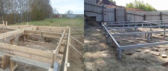
Possibility of using a single pile under a column (without grillage foundation, pile-column, etc.)
So, in the initial data we have a monolithic grillage x mm, height mm, supported by a single reinforced concrete pile with cross section x mm. A metal column rests on top of the grillage.
The column base and bolt spacing are shown in the figure below. Let's look at what design scheme should be adopted for the grillage. We have a rigid support on the pile. The load from the column is transmitted exactly along the axis of the pile, without piles.
But we have a bending moment that is transmitted through the foundation bolts, the position of which extends beyond the boundaries of the pile. In fact, if we depict the design diagram for the grillage, we will see the following. Considering that the design length of the console is equal to the overhang of the console, we will obtain for each console the following design scheme with pinching in the middle: We will have three loads: 1 uniformly distributed q s.
The length of each console is equal to the length of the grillage overhang. The binding of the vertical force P and the distributed load q is according to the actual bindings of the plate and bolts. Now we need to find the maximum bending moment M and the maximum shear force Q in the cantilever. To calculate the reinforcement, we will need the standard and design values of M and Q, highlighting permanent and temporary loads.
The load from your own weight is constant. For the convenience of calculating the console, we summarize the load on it in the table: Load Standard value Reliability factor for load Design value Initial data Constant load from its own weight q s.
How to read them? From the diagram of the moments we see that with such a load as in our example, when the moment tries to rotate the column counterclockwise, and it presses through the bolts on the left side of the grillage, while the right one tries to lift up, the maximum moment is in the left part of the grillage, Moreover, on the diagram it rises up above the zero line - which means it requires installing the upper working reinforcement along the grillage so that it absorbs the tension from bending. The moment on the diagram above means that the upper part of the section is stretched.
In the same way, on the right side of the grillage we see that the moment diagram first goes down, requiring lower working reinforcement, and then at the place where the bolt is installed, it rises up - tension appears there, requiring upper reinforcement. Thus, we need to install both upper and lower working reinforcement in the grillage.
We will calculate the upper one based on the value of M1, it is greater than M3, and the lower one based on the value of M2. From the shear force diagram we can see the need for shear reinforcement.
Download Series 1.411.1-7 Issue 0-2. Foundations for steel columns. Design materials
We have very stressed sections Q1-Q3 and Q2-Q5; they will have maximum transverse reinforcement. This is logical, since at points Q3 and Q5 we have concentrated forces from the bolts, and according to the design rules we must supply reliable transverse reinforcement from the support to the point of application of the concentrated load - this was confirmed by the calculation.
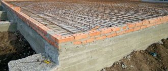
Let's take a look at the effort that went into our grillage. Having the calculation results in hand, we can calculate the reinforcement and start designing the grillage. Now we need to construct the grillage. The recommended reinforcement spacing in the grillage is mm. It is also recommended to reinforce the grillage with welded mesh; welding must be contact welding, and in no case - manual arc!
In addition, to anchor the working rods, a perpendicular rod of half the diameter compared to the working rods must be welded at a distance of 25 mm from their edge. Please note, since the grillage is not a slab, but a beam, we should not neglect the design requirements for the reinforcement of beams; they can be studied in the same manual.
Construction of general purpose reinforced concrete foundations with volume: up to 25 m3
LOCAL RESOURCE STATEMENT GESN 06-01-005-05
| Name | Unit |
| Construction of general purpose reinforced concrete foundations with volume: up to 25 m3 | 100 m3 of concrete and reinforced concrete in action |
| Scope of work | |
| 01. Cutting and installing boards 02. Installing formwork panels 03. Fastening formwork elements with wire and construction nails 04. Laying concrete mixture 05. Installing reinforcement. |
Foundation for a metal column
Now let's deal with transverse reinforcement; we will reinforce the grillage with welded frames, in which we will install transverse reinforcement with the pitch we need. When installing the frame into the formwork, do not forget about the need for a protective layer of concrete. Therefore, the reinforced frame must be raised from the base. To install the formwork, it is best to use steel elements that are connected by welding. Steel formwork has a high turnover rate.
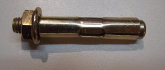
Wooden lumber can also be used to make small glasses. During installation, you should control the verticality of the formwork walls and mark the filling level of each step. One of the main elements that all foundations for metal columns have is an anchor, with the help of which the building frame elements are attached.
Construction of general-purpose reinforced concrete foundations for columns with a volume of up to 5 m3
LOCAL RESOURCE STATEMENT GESN 06-01-001-06
| Name | Unit |
| Construction of general-purpose reinforced concrete foundations for columns with a volume of up to 5 m3 | 100 m3 of concrete, rubble concrete and reinforced concrete in action |
| Scope of work | |
| 01. Cutting and installing boards 02. Installing formwork panels 03. Fastening formwork elements with wire and construction nails 04. Installing reinforcement 05. Laying concrete mixture |
The price indicates the direct costs of work for the period 2000
(Federal prices), which are calculated based on
2009
. The conversion index to current prices must be applied to this value.
Columnar foundation for columns
Columns are often used as loaded elements in the construction of not only industrial but also residential buildings and are installed with the same stringent requirements for reliability and permissible deviations from the design calculations, regardless of the method of their production and installation.
In standard construction, frame buildings are erected only for industrial purposes. With the development of the segment of individual buildings consisting of several floors of a large area, load-bearing supports in the form of columns, both in the houses themselves and in adjacent buildings, balconies, fences, canopies, and a garage for several cars, have become in demand. Often the frame structure of external walls and floor support is made in the form of pillars made of reinforced monolith with the gap between them filled with light aerated concrete blocks.
Pile foundation for columns
Uneven settlement of concrete pillars will lead to cracking of the wall material. Therefore, it is necessary to responsibly approach the correct construction of the foundation under the load-bearing elements, which are made in the form of pillars.
When designing the supporting part of a structure, standard factory-produced elements with already known characteristics and mounting loops for quick installation can be taken into account. The base for the column is selected based on the results of studies of the mechanical and dynamic characteristics of the underlying soils. The variety of options for the general design of foundations for columns is determined by the design features, area and shape of the future structure.
The dimensions of the sole for the standing support are chosen so that the load on the plane of contact with the ground does not exceed its load-bearing capacity. Typical indicators for shrinkage of each individual loaded element in the foundation did not exceed the permissible values specified in the standards.
The column can stand on a separate foundation or be located in a group for which there is a single base of strip or slab type. But the question still interested me, and I decided to write an article to develop design thinking with the assumption that our pile has already been calculated, designed, and can withstand all loads with a reserve. I will be glad to discuss in the comments.
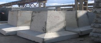
Construction of a prefabricated foundation
If you need to build a reliable and strong house as quickly as possible, use the technology of assembling a foundation from blocks. Before going to the factory to get them, it is necessary to calculate the reinforced concrete foundation. If you have never done this before, it is better to entrust this to a specialist or use an online calculator to find out the approximate number of blocks needed.
Most often, prefabricated reinforced concrete foundations are chosen for the construction of buildings that will have a basement or ground floor. By the way, it will not be possible to make a cool cellar with a monolithic base.
So, how does the construction of a prefabricated foundation take place:
- On the territory of the future house, the fertile layer of soil is removed and markings are made - pegs are stuck in the corners of the future walls, and a cable is pulled between them.
- Adhering to the created markings, they dig a pit with a flat bottom over the entire area of the future ground floor or basement.
- A sand embankment (pillow) is made along the perimeter of the pit, on which the delivered reinforced concrete blocks are installed.
- The blocks are fitted to each other as tightly as possible, and the seams are sealed with cement-sand mortar. Standard blocks have recesses along the entire height intended for filling vertical joints with mortar. Helpful advice: Experts recommend bandaging the seams of concrete blocks according to the same principle as installing brickwork.
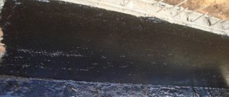
- From the outside, the resulting wall is covered with waterproofing material. This can be liquid bitumen mastic, modern roll materials or sprayed waterproofing. Penetrating waterproofing has recently become very popular - special liquid compounds that can penetrate inside a concrete wall, react with concrete and fill all the smallest pores.
- Next, you can begin building the walls and subfloor.
As you can see, the process itself is not at all complicated and quite fast, so if you want to save time, a prefabricated foundation is the best option.
When building a prefabricated foundation, you should remember the need to create technological openings for utilities - electricity, sewerage, water supply, gas, etc. To do this, a special case made of galvanized steel, plastic or ceramics is inserted into the block (other materials can be used, as long as they do not rust). After installing the cases according to the building design, they should be temporarily covered with tarred rags to prevent debris from getting inside. When all communications have been laid, the cases are caulked and ensure complete tightness.
8.1.3. Piles-columns
A column pile is a driven pile with non-prestressed reinforcement of square or hollow circular cross-section, the above-ground part of which serves as a column of a building or structure. The column pile differs from the corresponding tested pile in the presence of embedded parts and, if necessary, increased longitudinal reinforcement.
Rice. 8.2. Joints of composite piles
A
- glass;
b
- box-shaped;
c
- welded;
g
- bolted;
d
- adhesive;
e
- adhesive with an intermediate element; 1 - top link of the pile; 2 - pile frame; 3 - lower link of the pile; 4 - sheet; 5 - pipe; 6 - box; 7 - bolt; 8 - pin; 9 — hole with a diameter of 28/32 mm; 10 - intermediate element
A column pile operating in oblique eccentric compression must be reinforced with eight longitudinal rods.
TsNIIEPSelstroy has developed column piles with consoles for light agricultural buildings.
Column piles are recommended for use in medium-density sand and clayey soils of refractory and semi-solid consistency, as well as when cutting through loose sandy and soft-plastic clayey soils for craneless frame buildings with a load on the column of up to 500 kN, supports of structures with a load of up to 1000 kN, process pipelines with load up to 20 kN/m.
Rice. 8.3. Links of a composite pile with a glass joint
A
- top link;
b
- lower link
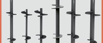
8.1.4. Bored piles
Bored piles are made in the ground. A reinforcement cage is installed in the drilled well and a concrete mixture is laid. After the concrete reaches its design strength, the pile can accept design loads (axial, pressing, pulling, horizontal).
Depending on the soil conditions and the available drilling equipment, which determine the manufacturing technology, bored piles are divided into several types: BSS, manufactured in stable clayey soils (dry); BSVG - in unstable clayey soils (water-saturated) with the walls of the wells secured with a clay solution; BSVO - in unstable soils (water-saturated) with the walls of the wells secured with pipes left in the ground; BSI - in unstable soils (water-saturated) with the walls of the wells secured with extractable pipes; BSSM - in stable clayey soils (dry) for lightly loaded buildings and structures.
Standard sizes of bored piles and the most common brands of drilling equipment are given in table. 8.4. The type and nomenclature of bored piles is taken depending on their economic efficiency, soil conditions, type and magnitude of operating loads, as well as the method of performing the work.
TABLE 8.4. NOMENCLATURE AND SIZES OF BORED PILES
| Pile type | Pile manufacturing method | Pile diameter1, mm | Concrete class | Pile length, m | Equipment |
| FSU | Rotary drilling in stable clay soils without securing the borehole walls | 500/1200 500/1400 500/1600 600/1600 | B15—B20 | 10—30 | SO-2 machines |
| 800/1800 1000 1200 | В15—В20 В15 В15 | SO-1200 machines | |||
| BSVG | Rotary drilling in unstable soils with fastening the borehole walls with clay solution | 600/1600 | B15—B20 | 10—20 | URB-ZAM machines |
| BSVO | Rotary and percussion-rope drilling in unstable soils with fastening the walls of the wells with pipes left in the ground | 600/1600 800/1800 | B15—B20 | 10—30 | Machines URB-ZAM, UKS |
| BSI | The same, with the removal of inventory casing pipes | 880 980 1080 1180 | B15 | 10—50 | Installation SP-45 and machines from foreign companies |
| BSSM | Rotary drilling in dry, stable clay soils without securing the borehole walls | 400 500 | B15 | 2—4 | Yamoburs |
1 The diameter of the trunk is indicated before the line, and the diameter of the widening is indicated behind the line.
Bored piles should be used in all cases where there are technical and economic advantages over other types of foundations.
Depending on the ground conditions, the following piles are accepted:
- – if it is necessary to cut through soils with a thickness of more than 20 m - BSS and BSVO with a length of 20-30 m, BSI with a length of 20-50 m;
- – when there is a difference in the roof of the load-bearing soil layer - all types of piles;
- – when supporting piles on clayey soils of hard, semi-solid and refractory consistency, on rocky, semi-rocky and sandy soils and cutting through: a layer of embankment with solid inclusions - BSVO, up to 30 m long and BSI 20-50 m long; layer of additive soils more than 10 m thick - BSS 12-30 m long; standing clay soils from soft plastic to fluid consistency more than 10 m thick - BSVG 15-20 m long, BSVO 15-30 m long and BSI 20-50 m long; layer of swelling soils - BSS 10-30 m long and BSSM - 3-6 m long with a widened heel.
Depending on the current conditions, the following piles are accepted:
- – BSS, BSVO, BSI when large (more than 100 kN) horizontal loads, including seismic ones, are applied to the pile;
- – BSS with diameters of 500 and 1200 mm, BSVO with diameters of 600 and 800 mm;
- – BSI with diameters of 880, 980, 1080 and 1180 mm for construction on landslide slopes;
- – BSI up to 20 m long for equipment foundations;
- – BSSM for lightly loaded structures.
Depending on the work conditions, bored piles are used:
- – in the absence of driven piles and equipment for driving them;
- – in cramped conditions of a construction site where driving piles is impossible;
- – when carrying out work near existing buildings and structures on which dynamic impacts arising during pile driving are unacceptable;
- – if it is necessary to strengthen the foundations of existing buildings.
Depending on the engineering and geological conditions, the characteristics of the designed building or structure and external loads transmitted to the foundations, bored piles are reinforced along the full length, part of the length, or only in the upper part for connection with the grillage (Table 8.5).
Reinforcing frames for bored piles are made, as a rule, in sections 6–12 m long. The design of the reinforcement frame for a bored pile is shown in Fig. 8.4. The joint of reinforcement frame links is carried out by welding the longitudinal rods of the lower frame with a stiffening ring located in the lower part of the upper link.
TABLE 8.5. FACTORS DETERMINING THE TYPE OF REINFORCEMENT FOR BORED PILES
| Type of reinforcement | Sketch | Ground conditions | Special site conditions | Pile loads | |||
| pulling out | compressive | horizontal | seismic | ||||
| To the full depth | Weak water-saturated soils throughout the entire depth of the piles | Presence of karst voids or underground workings along the depth of the pile | Predetermining reinforcement along the entire length | Stresses in concrete exceed the values specified in SNiP II-21-75, taking into account changes to SNiP II-17-77 | At tensile stresses in concrete σ t ≥ 0.4 MPa | In areas with seismicity more than 6 points (except for BSV piles) | |
| Top of the pile | The same, in the upper part of the pile to a depth of h | The presence of karst voids, underground excavations, channels, underground premises, etc. in the upper part of the pile. at depth h | Perceived by the reinforced part of the piles | Stresses in concrete do not exceed the values specified in SNiP II-21-75, taking into account changes to SNiP II-17-77 | The same, σ t < 0.4 MPa | None | |
| Without reinforcement | Cohesive soils with a flow index IL ≤ 0.4 | None | None | Same | Same | Same | |
Notes: 1. If there are karst voids or underground excavations along the length of the pile, casing pipes must be left.
2. On the sketches: 1—reinforcement outlets; 2 - reinforcement cages; 3 - individual reinforcing bars; d
— diameter of the reinforcement.
Rice. 8.4. Reinforcement frame of a bored pile
1 - longitudinal reinforcement; 2 — stiffening ring; 3 - spiral; 4 — protective layer retainer
The maximum frame length is set taking into account the adopted manufacturing technology and the availability of appropriate crane and transport equipment.
According to existing experience, the maximum length of the reinforcement cage for piles with a diameter of 500–600 mm is 14 m, with a diameter of 1000–1200 mm - 10 m. The recommended number of longitudinal reinforcement and its diameters are given in table. 8.6.
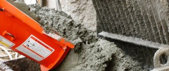
For bored piles, as a rule, cast concrete mixture with fine aggregate made from concrete of classes B10, B15 (the most common) and B20 is used.
The geometric characteristics and volumes of bored piles are given in table. 8.7, 8.8.
The cast concrete mixture is placed into the well using the vertically moving pipe (VPT) method with its continuous supply until the well is completely filled. In low-moisture, stable clay soils, free discharge of the concrete mixture into the well is allowed through a receiving hopper with a guide pipe approximately 2 m long, if the soil does not collapse from the walls of the well and the concrete mixture does not hang on the reinforcement frame. The possibility of using free discharge should be checked during the initial period of work in the presence of the project authors.
When making piles of the BSI type, it is necessary that the time for the concrete mixture to begin setting is at least 3 hours. To maintain the required plasticity and mobility of the concrete mixture, plasticizing and hydrophobic additives should be used.
TABLE 8.6. MATERIALS AND CHARACTERISTICS OF LONGITUDINAL REINFORCEMENT FOR BORED PILES
| Pile type | Pile diameter, cm | Concrete class | Longitudinal reinforcement class | Diameter of fittings, mm | Number of longitudinal rods, pcs. |
| BSSM | 40 | AT 10 | AI; A-II | 12; 14 | 6 |
| BSS BSSM | 50 | B10 B15 | A-I; A-III AI; A-II | 12; 14 | 6 |
| BSS BSVG BSVO | 60 | В10 В15 В20 | A-II; A-III | 14; 16; 18 | 6; 8; 10 |
| BSS BSVO | 80 | B15 B20 | 16; 18; 20 | 8; 10 | |
| BSI | 88 98 | B15 | 16; 18; 20 | 8; 10; 12 10; 12 | |
| FSU | 100 | B15 B20 | 16; 18; 20 | 10; 12; 14 | |
| BSI | 108 118 | B15 | 16; 18; 20; 22 16; 18; 20; 22; 25 | 12; 14; 16 | |
| FSU | 120 | B15 B20 | 16; 18; 20; 22; 25 | 12; 14; 16 |
TABLE 8.7. GEOMETRICAL CHARACTERISTICS OF BORED PILES
| Pile type | Diameter, mm | Sectional area, m2 | Widening height, m | Expansion volume, m3 | ||
| trunk | broadening | trunk | broadening | |||
| FSU | 500 | 1200 1400 1600 | 0,196 | 1,130 1,540 2,015 | 0,67 | 0,439 0,565 0,708 |
| 600 800 1000 1200 | 1600 1800 – – | 0,283 0,503 0,785 1,130 | 2,015 2,545 – – | 0,82 1,09 – – | 0,903 1,600 – – | |
| BSVG | 600 | 1600 | 0,283 | 2,015 | 0,60 | 0,679 |
| BSVO | 600 800 | 1600 1800 | 0,283 0,503 | 2,015 2,545 | 0,60 0,80 | 0,679 1,196 |
| BSI | 880 980 1080 1180 | – | 0,608 0,755 0,916 1,093 | – | – | – |
| BSSM | 400 500 | – | 0,126 0,196 | – | – | – |
TABLE 8.8. GEOMETRIC VOLUME OF CONCRETE BORED PILES
| Pile type | Pile diameter1, mm | Volume of concrete, m3, with pile length, m | ||||||||||
| 10 | 12 | 14 | 16 | 18 | 20 | 22 | 24 | 26 | 28 | 30 | ||
| FSU | 500 | 1,96 | 2,36 | 2,75 | 3,14 | 3,53 | 3,93 | – | – | – | – | – |
| 600 | 2,83 | 3,39 | 3,96 | 4,52 | 5,09 | 5,55 | – | – | – | – | – | |
| 500/1200 | 2,39 | 2,79 | 3,17 | 3,57 | 3,96 | 4,35 | 4,74 | 5,14 | 5,59 | 5,92 | 6,91 | |
| 500/1400 | 2,51 | 2,91 | 3,30 | 3,69 | 4,08 | 4,48 | 4,87 | 5,26 | 5,66 | 6,05 | 8,44 | |
| 500/1600 | 2,66 | 3,05 | 3,44 | 3,83 | 4,23 | 4,62 | 5,01 | 5,41 | 5,80 | 6,19 | 6,58 | |
| 600/1600 | 3,67 | 4,24 | 4,80 | 5,37 | 5,93 | 6,50 | 7,07 | 7,63 | 8,20 | 8,77 | 9,33 | |
| 800/1800 | 5,37 | 7,39 | 8,38 | 9,39 | 10,39 | 11,39 | 12,40 | 13,40 | 14,41 | 15,41 | 16,41 | |
| 1000 | 7,85 | 9,42 | 10,99 | 12,56 | 14,13 | 15,70 | 17,24 | 18,84 | 20,41 | 21,38 | 23,55 | |
| 1200 | 11,30 | 13,56 | 15,82 | 18,08 | 20,34 | 22,60 | 24,86 | 27,12 | 29,30 | 31,64 | 33,90 | |
| BSVG | 600/1600 | 3,51 | 4,08 | 6,54 | 5,21 | 5,77 | 6,34 | – | – | – | – | – |
| BSVO | 600/1600 | 3,51 | 4,08 | 4,64 | 5,21 | 5,77 | 6,34 | 6,91 | 7,47 | 8,04 | 8,60 | 9,17 |
| 800/1800 | 6,12 | 7,12 | 8,12 | 9,12 | 10,13 | 11,14 | 12,14 | 13,14 | 14,15 | 15,15 | 16,16 | |
| BSI | 880 | – | – | – | – | – | 12,16 | 13,37 | 14,59 | 15,80 | 17,00 | 18,20 |
| 980 | 15,08 | 16,59 | 18,10 | 19,60 | 21,11 | 22,62 | ||||||
| 1080 | 18,31 | 20,14 | 21,97 | 23,81 | 25,64 | 27,47 | ||||||
| 1180 | 21,85 | 24,05 | 25,23 | 28,42 | 30,60 | 32,79 | ||||||
1 The diameter of the trunk is indicated before the line, and the diameter of the widening is indicated behind the line.
The cast concrete mixture for bored piles should be transported in large-capacity concrete mixer trucks, the use of which ensures the placement of the mixture into the well without reloading operations. The distance from the place where the concrete mixture is prepared to the place where it is laid should be, if possible, no more than 3 km.