Pile reinforcement
The operating and installation conditions for driven and bored (or drilled injection) piles are different and determine the reinforcement.
SNiP 2-02-03 85
Reinforcement of driven structures
Incomplete (along the length) reinforcement is not allowed.
Additional reinforcement strengthens parts of the pile that experience increased loads: The upper part is reinforced with meshes (4-5 layers at a distance of 5 cm). Such reinforcement will allow the pile to better resist the blows of a pile driver; The lower part is reinforced with a conical cage connected to the reinforcement. This strengthens the tip of the pile, which during driving experiences significant loads when encountering stones and rocky soil.
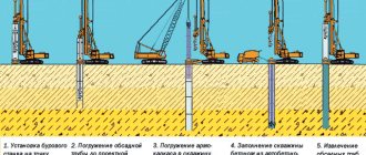
Reinforcement of bored and drilled injection structures
In case of homogeneous soils, incomplete reinforcement (lower part) is allowed for hanging piles.
a – pile – stand, b – hanging pile
A hanging pile is a pile supported on compressible soils due to friction. Unlike a stand pile, which rests its lower part on incompressible layers of soil.
The reinforcement scheme for bored and drilled injection piles repeats the reinforcement scheme for driven piles, but the following elements are missing:
- Reinforcement of the pile head with mesh;
- Mounting loops and centering pin;
- Conical cages at the bottom of the pile.
Longitudinal type reinforcement
In stable, medium-dense soil (loam, clay, sandy loam), longitudinal reinforcement can be used. This reduces the cost of the pile, but reduces the bending and tensile strength. Piles reinforced longitudinally are not allowed for use in the construction of hydraulic structures and in earthquake-prone areas.
With longitudinal reinforcement, the reinforcement frame consists of parallel rods forming a volumetric frame (piles up to 30x30 cm - 4 pieces and 6-8 pieces per pile 40x40 cm). The diameter of the reinforcing bars is 12-15 mm and class A300 (A-II) or A400 (A-III).
Reinforcement of longitudinal-transverse type
With longitudinal-transverse reinforcement of reinforced concrete, a spatial frame is made, from longitudinal (diameter 10-15 mm and class A300 (A-II) or A400 (A-III)) and transverse (diameter 6-8 mm and class A240 (AI) or from the same material as the longitudinal) reinforcement. It is permissible to use reinforcing mesh rolled into a cylinder (for round piles) if it fits the cross-sections of the longitudinal and transverse reinforcement.
Reinforcement using the prestress method
The use of prestressed longitudinal reinforcement will significantly increase the pile's resistance to tensile and bending loads. For prestressed reinforcement, steel 30-ХГ2С or 35-ГС is used. Size 13 – 20 mm.
In private construction, reinforced concrete with prestressed reinforcement is not often used.
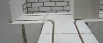
Reinforcement of the pile-grillage assembly
It is required to connect the longitudinal reinforcement of the pile and the longitudinal reinforcement of the grillage (1,3,5) using twisting or welding. The metal reinforcement of the pile is bent and connected to the longitudinal reinforcement of the grillage by welding or twisting with wire. For the reliability of the assembly, the length of the reinforcement must exceed 35 cm. Non-metallic reinforcement cannot be bent. In this case, they also connect the longitudinal reinforcement of the pile and the grillage at the intersection points and ensure that the pile reinforcement is embedded to a depth of at least 50 cm.
Driven reinforced concrete piles of square cross-section without transverse shaft reinforcement (p. 1)
STATE STANDARD OF THE USSR UNION
DRIVEN REINFORCED CONCRETE PILES OF SQUARE SECTION WITHOUT TRANSVERSE REINFORCEMENT OF THE BARREL
DESIGN AND DIMENSIONS
GOST 19804.4-78
USSR STATE COMMITTEE FOR CONSTRUCTION
Moscow
STATE STANDARD OF THE USSR UNION
| DRIVEN REINFORCED CONCRETE PILES OF SQUARE SECTION WITHOUT TRANSVERSE REINFORCEMENT OF THE BARREL Design | GOST 19804.4-78* |
By Resolution of the State Committee of the Council of Ministers of the USSR for Construction Affairs dated 01/01/01 No. 000, the implementation period was established
from 01.01.79
Failure to comply with the standard is punishable by law
This standard applies to driven reinforced concrete piles of square cross-section without transverse shaft reinforcement with prestressed reinforcement located in the center of the pile section.
The piles provided for by this standard are designed for bending strength and the formation of cracks from the forces that arise when lifting onto the pile driver at one point located from the end at a distance equal to 0.294 times the length of the prismatic part of the pile. The dynamic coefficient to the own weight is taken equal to 1.5, while the overload coefficient to the own weight is not introduced.
When designing pile foundations, piles must also be tested for strength and cracking under loads arising during the construction and operation of a building or structure.
When checking a pile for strength and the formation of cracks under eccentric compression from operational loads, it is allowed to use graphs 1-8 given in Appendix 3.
(Changed edition, Amendment No. 1).
1.1. The shape of the piles must correspond to that indicated in the drawing. 1, brand of piles, main dimensions, volume of concrete and reference mass - indicated in the table.
(Changed edition, Amendment No. 1).
1.2. Piles up to 7 m in length, inclusive, can be made without pins, and the slinging of the piles when lifting to the pile driver must be carried out at the top lifting loop.
1.3. The center of gravity of the longitudinal prestressing reinforcement should be located at the center of gravity of the cross section of the piles.
1.4. It is allowed to produce piles with a technological slope of two opposite sides of the cross-section not exceeding 1:20, without changing the cross-sectional area.
An example of the shape of a pile with a technological slope of 1:20 is given in Appendix 2.
Square piles without transverse shaft reinforcement
1 - lifting loops; 2 — pin for fixing the slinging point; 3 - longitudinal reinforcement.
Crap. 1
| Pile brand | Geometric dimensions, mm | Volume of concrete, m3 | Reference weight of the pile, t | |||
| L | 1 1 | L 2 | b | |||
| STs5-25; STspr5-25; STsko-25 | 5000 | 1000 | — | 250 | 0,32 | 0,80 |
| SC6-25; SCpr6-25; STsk6-25 | 6000 | 1200 | — | 250 | 0,38 | 0,95 |
| SC3-30; STspr3-30; STsk3-30 | 3000 | 600 | — | 300 | 0,28 | 0,70 |
| STs4-30; STspr4-30; STsk4-30 | 4000 | 800 | — | 300 | 0,37 | 0,93 |
| STs5-30; STspr5-30; STsk5-30 | 5000 | 1000 | — | 300 | 0,46 | 1,15 |
| STs6-30; STspr6-30; STsk6-30 | 6000 | 1200 | — | 300 | 0,55 | 1,38 |
| STs7-30; STspr7-30; STsk7-30 | 7000 | 1400 | 2100 | 300 | 0,64 | 1,60 |
| STs8-30; STspr8-30; STsk8-30 | 8000 | 1600 | 2400 | 300 | 0,73 | 1,83 |
| STs9-30; STspr9-30; STsk9-30 | 9000 | 1800 | 2600 | 300 | 0,82 | 2,05 |
| STs11-30; STspr11-30; STsk11-30 | 11000 | 300 | 3200 | 300 | 1,00 | 2.50 |
Notes:
1. Designation of pile grades - according to GOST 19804.0-78.
2. The letters in the pile mark mean:
SC - piles with rod reinforcement;
STspr - piles with wire reinforcement;
STsk - piles with reinforcement from ropes.
2.1. Piles must be manufactured in accordance with the requirements of this standard and GOST 19804.0-78.
2.2. Purpose, scope of application, general technical requirements, permissible deviations from design dimensions, test methods, marking, transportation and storage of piles must comply with those specified in GOST 19804.0-78.
2.3. Piles must be made of heavy concrete with a compressive strength of at least 300 kgf/cm2.
2.4. The tempering strength of concrete piles at the time of shipment from the manufacturer must be no lower than 100% of the design strength.
2.5. The following should be used as longitudinal prestressing reinforcement:
a) hot-rolled reinforcing steel of classes A-IV and AV according to GOST 5781-82;
b) high-strength reinforcing wire of class BP - II according to GOST 7348-81;
c) reinforcing ropes of class K-7 according to GOST. . It is also allowed to use thermally strengthened reinforcing steel of classes At-IV and At-V according to GOST.
2.6. Reinforcement diagrams with specifications and selection of reinforcement for each pile provided for by this standard are given in Appendix 1.
2.7. Tension of reinforcement of classes BP-II and K-7 should be carried out mechanically, tension of reinforcement of classes A-IV, AV, At-IV and At-V - by electrothermal or mechanical method.
2.8. The limiting value of reinforcement prestress s0 is accepted:
a) with mechanical tensioning method s0 = 0.95 RaII.
s0 = 0.95 RaII - for rod reinforcement,
s0 = 0.76 Ra II —
for wire reinforcement and ropes,
b) with the electrothermal method of tension
s0 =
RaII –300 — — for rod reinforcement,
where: RaII —
calculated tensile strength of reinforcement for limit states of the second group;
l
— length of the tension rod.
(Changed edition, Amendment No. 1).
2.9. The strength of concrete at the moment of releasing the tension of the reinforcement (transfer strength) must be at least 200 kgf/cm2.
2.10. After tension release, the reinforcement should be cut flush with the concrete of the tip and in the recess of the pile end.
2.11. The tensile force of the reinforcement for each brand of piles is indicated in Table. 1 applications 1.
2.12. The diameter of the longitudinal reinforcement must correspond to that given in table. 1 applications 1.
2.13. The distance between the axes of the wires must be at least 15 mm. The maximum distance from the center of gravity of the cross section of the pile to the axis of the most distant wire should not exceed 25 mm.
The distance between the axes of the ropes must be at least the diameter of the rope, but not more than 50 mm.
2.14. The head of the pile must be reinforced with wire meshes of class BI or BP-I with a diameter of 5 mm in accordance with GOST 6727-80.
The grids are installed in pairs, the number of grids is determined depending on the length of the pile in accordance with the table. 2 applications 1.
(Changed edition, Amendment No. 1).
2.15. The tip of the pile must be reinforced with a spiral of BI class wire with a diameter of 5 mm in accordance with GOST 6727-80.
2.16. Loops for lifting piles, pins and a spiral at the tip of the pile must be tied to the longitudinal reinforcement of the pile with knitting wire.
2.17. For hinges, hot-rolled reinforcing steel of class AI, grades VSt3sp2 and VSt3ps2, should be used.
In case of transportation of piles at a temperature of -40°C and below, it is not allowed to use steel grade VSt3ps2.
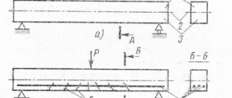
3.1. In accordance with GOST 19804.0-78, piles must be tested for cracking by laying them on two supports according to Fig. 2.
Pile testing scheme
Crap. 2
3.2. After laying the piles on two supports, a thorough inspection of its upper edge above the supports is carried out. The pile is considered to have passed the test if no cracks appear on its edges.
When reinforcing piles, the following requirements must be met:
1. The reinforcement scheme for driven reinforced concrete piles without transverse reinforcement of the shaft must correspond to that shown in the drawing of this appendix. The number of meshes in the head of the pile is shown conditionally. The formwork dimensions of the piles are given in the table of this standard.
2. The specification of reinforcement products for piles must correspond to the given and table. 1 of this appendix.
3. The selection of steel for piles with various options of longitudinal reinforcement is given in table. 2 of this appendix.
4. Drawings of reinforcement products, a list of rods for each element of reinforcement products and a selection of steel are given in table. 3 and 4 of this appendix.
1.-4. (Nominal edition, Amendment No. l).
Pile reinforcement scheme
Table 1
Specification of reinforcement products for piles
| Geometric dimensions of the pile, mm | Length of longitudinal reinforcement, mm | Options for longitudinal reinforcement classes | Pile head reinforcement | Tip fittings (1 pc.) | Hinges (2 pcs.) | Pin (1 piece) | |||||||||||||
| A-IV (At - lV) | AV (At-V) | Bp-II | K-7 | ||||||||||||||||
| L | b | Quantity, diameter, mm | Tension force, tf | Quantity, diameter, mm | Tension force, tf | Quantity, diameter, mm | Tension force | Quantity, diameter, mm | Tension force | Brand | Quantity | ||||||||
| Mechanical method | Electrothermal method | Mechanical method | Electrothermal method | Single wire | Everyone | One rope | everyone | ||||||||||||
| 5000 | 250 | 5250 | 1Æ10 | 4,5 | 4,0 | 1Æ10 | 6,0 | 5,5 | 2Æ5 | 2,4 | 4,7 | 1Æ9 | 6,8 | — | S25 | 6 | Sc | PC1 | — |
| 6000 | 250 | 6250 | 1Æ12 | 6,5 | 5,8 | 1Æ12 | 8,6 | 8,1 | 3Æ5 | 2,4 | 7,2 | 1Æ9 | 6,8 | — | S25 | 6 | Sc | PC1 | — |
| 3000 | 300 | 3250 | 1Æ10 | 4,5 | 3,7 | 1Æ10 | 6,0 | 5,2 | 2Æ5 | 2,4 | 4,7 | 1Æ6 | 3,2 | — | C30 | 4 | Sc | PC2 | — |
| 4000 | 300 | 4250 | 1Æ10 | 4,5 | 3,8 | 1Æ10 | 6,0 | 5,4 | 2Æ5 | 2,4 | 4,7 | 1Æ9 | 6,8 | — | C30 | 4 | Sc | PC2 | — |
| 5000 | 300 | 5550 | 1Æ12 | 6,5 | 5,7 | 1Æ10 | 6,0 | 5,5 | 3Æ5 | 2,4 | 7,2 | 1Æ9 | 6,8 | — | C30 | 6 | Sc | PC2 | — |
| 6000 | 300 | 6250 | 1Æ14 | 8,8 | 7,9 | 1Æ12 | 8,6 | 8,1 | 4Æ5 | 2,4 | 9,2 | 1Æ12 | 11,8 | — | C30 | 6 | Sc | PC2 | — |
| 7000 | 300 | 7250 | 1Æ16 | 11,5 | 10,5 | 1Æ12 | 8,6 | 8,2 | 6Æ5 | 2,4 | 14,3 | 1Æ12 | 11,8 | — | C30 | 6 | Sc | PC3 | Shts |
| 8000 | 300 | 8250 | 1Æ16 | 11,5 | 10,6 | 1Æ14 | 11,7 | 11,2 | 6Æ5 | 2,4 | 14,3 | 1Æ12 | 11,8 | — | C30 | 6 | Sc | PC3 | Shts |
| 9000 | 300 | 9250 | 1Æ18 | 14,5 | 13,5 | 1Æ16 | 15,3 | 14,7 | 8Æ5 | 2,4 | 19,1 | 1Æ15 | 17,7 | — | C30 | 6 | Sc | PC3 | Shts |
table 2
| Due to its large volume, this material is placed on several pages: 1 |
Calculation
Let's look at the example of calculating reinforcement. You can take the parameters necessary for the calculation in your project. For our example we will assume the following:
- 16 piles in our foundation;
- Pile pitch – 2 meters;
- Pile height – 2 meters;
- The diameter of the pile is 20 centimeters.
Reinforcement will be carried out evenly along the entire length. The grillage-pile connection will require at least 35 cm for longitudinal reinforcement. Based on SNiP, reinforcement of a bored pile of this diameter must be carried out with at least 4 rods. 2.35*4=9.4 meters for one column, and 16*9.4=150.4 meters for all 16 piles.
In order not to waste time with scraps, take reinforcement 5-15% more than calculated.
We will consider the longitudinal reinforcement scheme. The reinforcement frame must have jumpers (clamps) with a step of 1 meter to maintain its shape. The jumper (clamp) is a circle or polyhedron (for 4 bars of longitudinal reinforcement, in our case a square). 3.14*0.2=0.63 meters – for one lintel or 0.63*3=1.9 meters – for one bored pile. 16*1.9=30.4 meters – for all 16 piles. To connect, use either welding or binding wire with a diameter of 1.2-1.7 mm. One twist will require about 30 cm of wire. 12*0.3*16=57.6 meters – for 16 bored piles. If you want to widen the pile at the bottom, you will need 10-15% more reinforcement.
Compression and rupture of piles
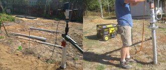
As mentioned above, to carry out work on reinforcing bored piles, it is necessary to first drill a well. On the modern construction market you can easily find many different drills (manual, gasoline or electric) at the most affordable prices.
It is known that piles cope well with mechanical deformation in tension and compression. In contrast, the foundation can only cope with compression. It is by combining the two structures that it is possible to achieve high levels of resistance to severe frost heaving or heaving in loose soils. Bored piles with a diameter of 30 cm have shown themselves to be very good for solving such problems. It is this diameter that makes it possible to cope with excessive loads in almost any conditions.
Reinforcement using the vertical method shows maximum strength
To impart maximum strength, it is necessary to carry out reinforcement using the vertical method. To do this, use reinforcement with a diameter of 1 cm (sometimes 1.2 cm). Smooth rods are used to fasten reinforcement into a single structure every 1 meter. The diameter of the smooth rods can vary from 6 to 8 mm, and the length - up to 8 cm. Thus, it is possible to create a reliable, rigid, durable metal structure on a budget, which will subsequently be immersed directly into the well cavity.
So, despite the relative complexity of the process of creating such a reinforcing structure, its main advantage is its low cost compared to technologies for strengthening the foundation. To create it, they use very affordable materials that can be purchased at any hardware store, which allows it to be used in the construction of frame houses, cottages, garages, bathhouses and country houses.
It is thanks to their resistance to high compressive and tensile loads that bored piles with a diameter of 300 mm have become so popular. Remember that a standard concrete foundation is practically unable to withstand these types of loads, which leads to its rapid destruction. Such destruction often leads to the appearance of high humidity, fungus, mold, loss of temperature and many other negative consequences that can significantly worsen the microclimate in the room.
Agree that the minimal financial losses that you may incur during the creation and installation of bored piles is an adequate price for comfort and convenience for many years of your life in your future home.
Making frames
Let's consider creating a spatial frame for reinforcing the pile. Be sure to take into account the protective layer of concrete (3 - 5 cm). The layer between the reinforcement and the outer surface of a reinforced concrete product. Your frame should be smaller than the internal dimension of the formwork to provide a protective concrete layer. The length of the longitudinal reinforcement must be at least 35 cm greater than the length of the pile. Coating the reinforcement with an anti-corrosion compound will extend the service life of the foundation. We recommend doing this:
- cut longitudinal rods to size;
- bend the clamps onto the mandrel (prepare all the clamps for at least 1 pile);
- if a driven pile is reinforced, then set aside a distance from the ends for reinforcement with mesh and for a conical cage at the tip;
- secure the clamp (by welding or wire), step back one step of the transverse reinforcement and secure the next clamp, make sure that the frame does not lose its shape;
- if a driven pile is being reinforced, secure the mesh to the cap and the collar to the tip, mounting loops and a centering pin if used.
Types of reinforced concrete piles
Precast concrete piles are classified as follows:
- C – have a square cross-section, can be solid or composite, and have transverse reinforcement.
- SC - they also have a square cross-section, the reinforcement is stressed in the center, there is no cross-section.
- SK - this pile with a circular cross-section can be either solid or composite.
- CO are shell piles, characterized by a large diameter (from 1000 to 3000 mm), and can be solid or composite.
- SD1 is a column pile with a square cross-section, installed at the corners of buildings.
- CD2 – columns designed for installation along the central axis of buildings.
- SP - piles with a cavity, have a square cross-section, only solid.
Grillage reinforcement
Reinforcement of the pile cap is also necessary to increase the load-bearing capacity. You should not count on the reliability of grillage elements without reinforcing elements; they are not able to withstand high loads from walls. To solve the problem, reinforcement with a diameter of 10-12 or 14 mm is used.
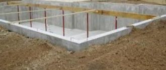
A strip-pile foundation involves making a frame for a grillage from an upper and lower chord, which are connected by vertical rods 6-8 mm in diameter.
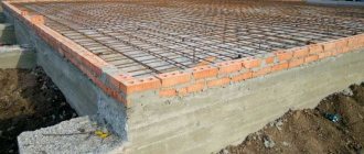
Reinforcing a grillage on piles, which has the shape of a slab, is quite expensive due to the high costs of concrete and reinforcement. The principle of their strengthening is similar to the reinforcement of strip-pile foundations.
Our company offers you high-quality foundation strengthening with a guarantee of results. We also calculate the reinforcement of a bored pile so that you can be sure that your house will stand for a long time.
TECHNICAL REQUIREMENTS
2.1. Piles must be manufactured in accordance with the requirements of this standard and GOST 19804.0-78.
2.2. Purpose, scope of application, general technical requirements, permissible deviations from design dimensions, test methods, marking, transportation and storage of piles must comply with those specified in GOST 19804.0-78.
2.3. Piles must be made of heavy concrete with a compressive strength of at least 300 kgf/cm2.
2.4. The tempering strength of concrete piles at the time of shipment from the manufacturer must be no lower than 100% of the design strength.
2.5. The following should be used as longitudinal prestressing reinforcement:
a) hot-rolled reinforcing steel of classes A-IV and AV according to GOST 5781-82;
b) high-strength reinforcing wire of class VR-II according to GOST 7348-81;
c) reinforcing ropes of class K-7 according to GOST 13840-68. . It is also allowed to use thermally strengthened reinforcing steel of classes At-IV and At-V according to GOST 10884-81.
2.6. Reinforcement diagrams with specifications and selection of reinforcement for each pile provided for by this standard are given in Appendix 1.
2.7. Tension of reinforcement of classes BP-II and K-7 should be carried out mechanically, tension of reinforcement of classes A-IV, AV, At-IV and At-V - by electrothermal or mechanical method.
2.8. The limiting value of reinforcement prestress s0 is accepted:
a) with mechanical tensioning method s0 = 0.95 RaII.
s0 = 0.95 RaII - for rod reinforcement,
s0 = 0.76 Ra II —
for wire reinforcement and ropes,
b) with the electrothermal method of tension
s0=
RaII –300 — — for rod reinforcement,
where: RaII —
calculated tensile strength of reinforcement for limit states of the second group;
l
— length of the tension rod.
(Changed edition, Amendment No. 1).
2.9. The strength of concrete at the moment of releasing the tension of the reinforcement (transfer strength) must be at least 200 kgf/cm2.
2.10. After tension release, the reinforcement should be cut flush with the concrete of the tip and in the recess of the pile end.
2.11. The tensile force of the reinforcement for each brand of piles is indicated in Table. 1 applications 1.
2.12. The diameter of the longitudinal reinforcement must correspond to that given in table. 1 applications 1.
2.13. The distance between the axes of the wires must be at least 15 mm. The maximum distance from the center of gravity of the cross section of the pile to the axis of the most distant wire should not exceed 25 mm.
The distance between the axes of the ropes must be at least the diameter of the rope, but not more than 50 mm.
2.14. The head of the pile must be reinforced with wire meshes of class BI or BP-I with a diameter of 5 mm in accordance with GOST 6727-80.
The grids are installed in pairs, the number of grids is determined depending on the length of the pile in accordance with the table. 2 applications 1.
(Changed edition, Amendment No. 1).
2.15. The tip of the pile must be reinforced with a spiral of BI class wire with a diameter of 5 mm in accordance with GOST 6727-80.
2.16. Loops for lifting piles, pins and a spiral at the tip of the pile must be tied to the longitudinal reinforcement of the pile with knitting wire.
2.17. For hinges, hot-rolled reinforcing steel of class AI, grades VSt3sp2 and VSt3ps2, should be used.
In case of transportation of piles at a temperature of -40°C and below, it is not allowed to use steel grade VSt3ps2.