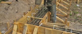
Calculation of loads on formwork
Calculation of loads on formwork
When calculating formwork, scaffolding and fastenings, the following standard loads must be taken.
a) own weight of formwork and scaffolding, which is determined from the drawings. When constructing wooden formworks and scaffolding, the volumetric mass of wood should be taken: for coniferous species - 600 kg/m 3, for deciduous species - 800 kg/m 3;
b) the mass of freshly laid concrete mixture, accepted for concrete on gravel or crushed stone from hard rocks, is 2500 kg/m 3, for concrete of other types - according to the actual weight;
c) the weight of reinforcement accepted according to the project, and in the absence of design data - 100 kg/m 3 of reinforced concrete structure;
d) loads from people and vehicles when calculating the deck, decking and scaffolding elements directly supporting them – 2.5 kPa; decks or flooring when calculating structural elements - 1.5 kPa.
Notes
? The deck, decking and directly supporting elements must be checked for concentrated load from the mass of a worker with a load (1300 N) or from the pressure of the wheels of a two-wheeled cart (2500 N) or other concentrated load, depending on the method of supplying the concrete mixture (but not less than 1300 N ).
? When the width of the deck or deck boards is less than 150 mm, the specified concentrated load is distributed over two adjacent boards;
e) loads from vibration of the concrete mixture - 2 kPa on a horizontal surface (taken into account only in the absence of loads according to paragraph “d”).
f) standard wind loads;
g) the pressure of the freshly laid concrete mixture on the side elements of the formwork, determined according to table. 3.15.
Table 3.15. Pressure of freshly laid concrete mixture on the side elements of the formwork
Designations adopted in table. 3.15:
? P – maximum lateral pressure of the concrete mixture, kPa;
? ? – volumetric mass of the concrete mixture, kg/m3;
? H – height of the laid layer of concrete mixture exerting pressure on the formwork, m;
? v – speed of concreting the structure, m/h;
? R, R 1 are the operating radii of the internal and external vibrator, respectively, m;
? K 1 – coefficient taking into account the influence of the consistency of the concrete mixture: for a rigid and slow-moving mixture with a cone settlement of 0–2 cm – 0.8; for mixtures with a cone draft of 4–6 cm – 1; for mixtures with a cone draft of 8-12 cm – 1.2;
? K 2 – coefficient for concrete mixtures with temperature: 5–7 °C – 1.15; 12–17 °C – 1; 28–32 °C – 0.85.
Note. The specified loads should be taken into account only in the absence of loads according to paragraph “and”;
h) loads from vibration of the concrete mixture - 4 kPa on the vertical surface of the formwork.
In case of external vibration, the load-bearing elements of the formwork (ribs, screeds, clamps, etc.), their fastenings and connections must be additionally calculated for the local effects of vibrators. Loads are taken according to the law of hydrostatic pressure.
Table 3.16. Selection of the most unfavorable combinations of loads when calculating formwork and supporting scaffolding
In all cases, the pressure value of the concrete mixture should be limited to the value of hydrostatic pressure P max =.
resulting pressure with a triangular diagram
i) loads from vibrations that occur when laying concrete mixture into the formwork of a concrete structure (accepted according to Table 3.17).
Table 3.17. Loads from vibrations occurring when laying concrete mixture into the formwork of a concrete structure
The specified dynamic loads must be taken into account in full when calculating the deck boards and the ribs supporting it. Beams (purlins) supporting the ribs should be calculated in accordance with the actual design of the structures, taking into account dynamic impacts in the form of concentrated loads from two adjacent ribs with a distance between them of up to 1 m and from one rib with a distance between the ribs of 1 m or more. In this case, the most unfavorable location of these cargoes should be taken into account.
Structural elements that serve as supports for beams (purlins), for example struts, ties, etc., should be designed for load from two adjacent ribs located on both sides of the element being calculated (with a distance between the ribs of less than 1 m), or from one rib closest to this element (with a distance between the ribs of 1 m or more).
The selection of the most unfavorable combinations of loads when calculating formwork and supporting scaffolding should be carried out in accordance with Table. 3.18.
Table 3.18. Selection of the most unfavorable combinations of loads when calculating formwork and supporting scaffolding
When calculating formwork and scaffolding elements according to their load-bearing capacity, the standard loads listed above must be multiplied by the overload factors given in Table 3.19. With the combined action of useful and wind loads, all design loads, except for the own mass, are entered with a coefficient of 0.9.
When calculating formwork and scaffolding elements for deformation, standard loads are taken into account without multiplying by overload factors.
The distribution of pressure along the height of the formwork is adopted by analogy with hydrostatic pressure along a triangular diagram.
Table 3.19. Overload factors
The deflection of formwork elements under the influence of perceived loads should not exceed the following values:
? 1/400 of the span of the formwork element;
? 1/500 span for floor formwork.
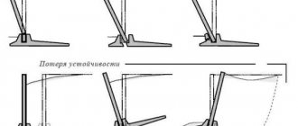
Calculation of scaffolding and formwork for stability against overturning should be carried out taking into account the combined effect of wind loads and its own weight, and when installing formwork together with reinforcement, also the weight of the latter. Overload factors should be taken equal: for wind loads - 1/2, for holding loads - 0.8.
The calculation of the formwork-cladding remaining in the body of the structure must be performed as a calculation of the main elements of the structure, followed by a check for the impact of the loads listed above.
To calculate devices that ensure preliminary separation of the shutters of block forms of large-panel formwork, volumetric-adjustable and tunnel formwork, the standard loads should be taken according to table. 3.20 and 3.21.
Table 3.20. Standard loads for calculating devices that provide preliminary separation of the shutters of block forms of large-panel formwork, space-adjustable and tunnel formwork
Above the line - for concrete class B7.5, below the line - for concrete class B20.
Table 3.21. Coefficient taking into account the tearing conditions and the degree of rigidity of the formwork
Note. To determine the calculated values of the tangential adhesion load, the data in Table. 3.21 should be multiplied by a factor of 1.35.
The calculated resistances of materials are accepted with a coefficient K. The increase in calculated resistances for a short duration of the load K for wood materials is taken equal to 1.4.
It is recommended to determine the force of separation of the formwork from the concrete using the formula:
where K co is a coefficient that takes into account tearing conditions and the degree of rigidity of the formwork (determined according to Table 3.21);
? n – standard clutch load, kPa;
Fc – contact area of the formwork with concrete, m2.
To calculate the breaking forces of rolling formwork, standard loads should be taken according to table. 3.22.
Table 3.22. Standard loads for calculating the breaking forces of rolling formwork
* For concrete class B10.
This text is an introductory fragment.
The pressure of the vibrating concrete mixture on the formwork
To determine the pressure of the vibrating concrete mixture on the formwork, a device is used, the diagram of which is. The device consists of a metal glass with a spherical rubber diaphragm at the end and a tee connecting the glass to a pressure gauge. The glass and tee are adjacent to a round metal plate with a diameter of 200 mm, which serves to strengthen the device on the formwork. The rubber bulb used to adjust the device is closed with a tap. The cavities of the glass and tee are filled with water. The device is secured with screws to the wall of the formwork 8, and a rubber ring is inserted into the groove between the plate and the board. The pressure of the concrete mixture on the diaphragm is transmitted through an intermediate medium to a pressure gauge, from which readings are taken. Experiments carried out in a column with a cross-section of 25x25 cm and a height of 4 m showed that at the moment the vibrator is started, the pressure drops slightly due to the fact that the concrete does not follow the formwork in its vibrations, and then, as the concrete mixture is compacted, the pressure increases to a certain limit. In the final period of vibration, the pressure is 0.02-0.04 kg/cm2 less than after the cessation of vibration. Prolonged vibration with loose formwork leads to leakage of laitance and a decrease in pressure. The absolute value of pressure and the nature of its distribution over height depend on the limit of vibration propagation, called the “radius of action of the vibrator.”
The mobility of the concrete mixture does not affect the nature of the pressure distribution along the height. The concrete composition with a mobility of 0-1 cm had the same pressure as the composition with a mobility of 5-7 cm. The maximum absolute pressure in both cases was equal to 0.55 kg/cm2. Lower absolute pressure values for cast concrete mixture with a settlement of 15-18 cm were obtained due to the looseness of the formwork. The pressure of the vibrating concrete mixture on the formwork wall corresponds to the pressure of a liquid with a specific gravity equivalent to the volumetric weight of the laid concrete. The experiments were carried out on concrete with crushed stone, with a specific gravity of 2.8, as a result of which high absolute values of volumetric weights were obtained (2,500 kg/m3).
Experiments on concrete with river gravel, which had a reduced volumetric weight, made it possible to compare identical compositions with different volumetric weights and different compositions with the same volumetric weight. Layout of vibrators and devices. A comparison of pressure curves for two identical compositions, differing in volumetric weight, showed that both curves coincide to a certain extent with the theoretical straight line of liquid pressure. This limit depends on the vibration propagation limit. Two other concrete mixture compositions had similar volumetric weights (2,400 for the first and 2,350 for the second) at different cement consumption (14 and 12%). Comparing the pressure curves for compositions with 12 and 14% cement, it was found that the nature of the pressure distribution along the height does not change with changes in the composition of the mixture. Considering the possibility of using mixtures with a lower sand content, which is advisable for vibrated concrete, an experiment was carried out on a mixture containing 30% sand.
The readings of both devices corresponded well to the direct pressure of the liquid with a volumetric weight of 2,400 kg/m3. Up to a height of 1.6 liters, the mold was filled with concrete mixture by bayoneting without vibration. The pressure of the concrete mixture during manual placement increased in proportion to the thickness of the laid layer up to a height of 50 cm. Up to a filling height of 2.75 m (above the lower device), the pressure of the vibrating concrete followed the law of hydrostatic fluid pressure. Further filling of the concrete mixture and vibration did not cause an increase in pressure. Excessive vibration of the lower layers, despite the careful manufacturing of the formwork, caused water leakage and decreased pressure.
It can be considered established that the mobility of the concrete mixture and its composition during vibration do not affect the nature of the pressure distribution along the height. The absolute pressure values depend on the volumetric weight of the compacted concrete and the limit of vibration propagation. In accordance with this, the absolute pressure values for different compositions and at different mobility can be determined by the volumetric weight of the concrete and the radius of action of the vibrator.
Friction between the walls of the mold and adjacent particles of the mixture during vibration is reduced to a minimum. Therefore, the dimensions of the molds should not affect the pressure distribution along the height, which was confirmed by the experiments.
A comparison of pressure curves for molds with a cross-section of 25x25 and 30x30 cm shows that the dimensions of the molds do not affect the pressure distribution along the height. The slight difference in the sizes of the forms does not allow us to extend this conclusion to forms of a larger cross-section. To generalize the conclusion, an experiment was carried out in a column with a cross section of 50X50 cm, 4 m high. The results of the test in a column with a cross section of 50X50 cm were compared with the results of the experiment carried out in a column of 30X30 cm. Pressure curves were constructed. The influence of mold sizes affects the limit of vibration propagation with a vibrator of a given power, but not the law of pressure distribution over height.
The residual pressure of concrete on the formwork decreases 1.5-2 hours after laying to a minimum equal to 60% of the initial pressure, and after 4 hours it increases again to 75% of the original value. In absolute value, the minimum is 0.4 kg/cm2; after 4 hours the pressure rises to 0.6 kg/cm2.
The large residual pressure should have caused some difficulties during stripping, which in reality was not observed.
The experiments were carried out on a column with a cross section of 30x30 cm with a concrete mixture of composition 1:2.5:4.8, with a cone draft of 2 cm. The maximum pressure at the bottom of the column after filling with the concrete mixture was 0.43 kg/cm2. Observations were carried out for 18 hours. with readings at the beginning of the test after 15 minutes, and then after 30 minutes. and 2 hours. Curves of pressure changes over time were constructed. The residual pressure of vibrated concrete (curve) is small. 4 hours after installation, the pressure was 54% of the original. After 14 hours. the pressure dropped to 0.09 kg/cm2 (20% of the original).
The second experiment was carried out in a column of the same cross-section, but with a concrete mixture of composition 1: 3.06: 5.94, with a slump of 2 cm. The residual pressure change curve is shown. From a comparison of the residual pressure change curves for concrete with 12 and 10% cement, it can be seen that in the first case the curve drops down more steeply. Residual pressure after 18 hours. in the first case it turned out to be 0.09 kg/cm2 versus 0.19 kg/cm2 in the second. This can be explained by the fact that in concrete with high cement consumption, shrinkage phenomena occur more intensely, and the absolute value of shrinkage is greater, which affects the decrease in pressure on the formwork wall. The shrinkage of concrete does not stop by 18:00. By the time of formwork, you can expect a decrease in the residual pressure on the wall.
To check the effect of concrete composition (cement content) on the residual pressure, an experiment was carried out with a composition of 1: 3.06: 5.94 in a column with a section of 30x30 cm. The last two compositions with the same cement consumption (10% of the weight of the dry mixture) showed residual pressure after 18 hours. 0.19 and 0.21 kg/cm2, and at the end of concreting at 0.36 and 0.4 kg/cm2.
Expressed as a percentage of residual pressure after 18 hours. at 10% cement content in the mixture is on average 50% of the maximum versus 20% after 14 hours. at 12% cement.
Pressure on the formwork wall during internal vibration. The nature of the pressure distribution over height when laying a concrete mixture with internal vibrators is somewhat different from external vibration.
| << PREVIOUS CHAPTER Vibrotransport installations | NEXT CHAPTER >> Internal vibrator (pervibrator) |
Calculation of concrete pressure on the formwork walls
When calculating formwork, the primary task is to determine the load that will be exerted on its complex. The calculation data is obtained taking into account many factors, including: the weight of the formwork components, the weight of the concrete mixture, the weight of the reinforcing elements, as well as the total weight of the scaffolding and workers involved in pouring. In addition, to ensure the stability of the structure and calculate the required number of supporting elements, it is necessary to calculate the wind load indicator. In general, the load experienced by the formwork is divided into vertical and horizontal.
Calculation of the maximum lateral pressure of concrete on the formwork walls
| Sealing method | Calculation formulas for determining the maximum lateral pressure of a concrete mixture, kPa | Limits of application of the formula |
| Using vibrators: | P = γH P = γ(0.27 + 0.78)К1К2 | |
| internal | Н ≤ R ν 4.5 provided that Н > 2 m |
- P
—maximum lateral pressure of the concrete mixture, kPa; - γ
—volumetric mass of the concrete mixture, kg/m³; - H
is the height of the laid layer of concrete mixture exerting pressure on the formwork, m; - ν
— speed of concreting the structure, m/h; - R, R
1 - respectively, the radii of action of the internal and external vibrator, m; - K
1 - coefficient taking into account the influence of the consistency of the concrete mixture: for a rigid and low-moving mixture with a cone draft of 0-2 cm - 0.8; for mixtures with a cone draft of 4-6 cm - 1; for mixtures with a cone draft of 8-12 cm - 1.2. - K
2 - coefficient for concrete mixtures with temperature: 5-7 ° C - 1.15; 12-17°C - 1; 28-32°C - 0.85.
Lateral pressure of concrete on the formwork.
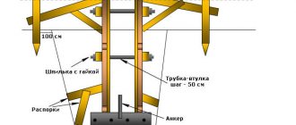
For formwork heights below 2.40 m, the bottom row of strands of recumbent elements is located directly above the ground. You can get out of this situation with the help of cm-high beams that are placed under the formwork. If elements with a height of 1.20 m standing are used, then there is no such problem; these elements must be placed so that the lower anchor holes are at a height of 30 cm from the ground.
With such a lifting of the strands, the concrete should be laid immediately to a height of at least 70 cm or in inclined layers, otherwise the higher pressure below when compacting the concrete can lead to the formwork becoming trapezoidal. It is much more difficult if there is no way to install the lower strands in the trenches. Local external fastening is then required. It should be taken into account that there are no floating forces caused, for example, by strongly inclined struts.
The top anchorage can be moved up above the formwork using AN hangers. If standard tie materials such as DW 15 are replaced with local wire, which is often done for large-sized foundations, then the possibility of extending these materials is taken into account. In my experience, although I won’t say that it’s very rich, it is.
In addition, you have probably already decided which places on the perimeter you will supply concrete - there you can strengthen it more abruptly. Sorry if I tell you the truism: the ties must cling to the vertical posts of the shields.
All rights reserved.
Translation: zCarot. Experiences of engineer S.
Vertical load
This concept means the total load exerted on the supporting elements of vertical formwork systems by structural elements, pouring mixture and other operating factors. The design components of the vertical load include:
- Total weight of a complex of formwork elements . The weight of each component part is indicated in the technical documentation. When using wooden formwork, the weight is calculated according to the constants approved in SNIP: 800 kg/cub.m. – for hardwood, 600 kg/cub.m. – for coniferous wood varieties.
- Mass of reinforcing elements . Indicated in the design data or calculated using a constant for reinforced concrete structures equal to 100 kg/m3 (in the absence of exact data).
- The load exerted by transport and human labor. The nomenclature value of this indicator may differ for the calculation of specific formwork elements or their complex. In this case, values of 1.5 kPa and 2.5 kPa are considered, respectively.
- Concrete mass - calculated by the actual weight of the components or using nomenclature data, for concrete mixtures with crushed stone or gravel (2500 kg/cub.m.).
Horizontal load
This set of influencing factors includes:
- wind load, whose value is calculated according to SNiP 2.01.07-85;
- indicator of concrete pressure on the walls of the formwork, for the calculation of which the following formula is used:
dB = mV where,
- db – the required indicator of concrete pressure kPa;
- m is the volumetric mass of the concrete mixture, kg/m3;
- B is the height of the concrete layer, m.
Horizontal load on side formwork
| Method of supplying concrete mixture to formwork | Horizontal load on side formwork, kPa |
| Descent along chutes and trunks, as well as directly from concrete pipes | 4 |
| Unloading from buckets with a capacity, m³: from 0.2 to 0.8 sv. 0.8 | 4 6 |
Also considered horizontal are vibration loads that occur when compacting a concrete mixture with special vibrating tools.
How to calculate concrete pressure on formwork
The experiments were carried out under conditions of construction of a waterworks complex during compaction of the concrete mixture without vibration. Stepanov notes the following phenomena: The above do not fully reflect the influence of all the above factors on the magnitude and nature of pressure and at present can no longer satisfy the requirements for designing formwork for massive hydraulic structures.
None of these takes into account the phenomenon of residual pressure, while taking it into account makes it possible to greatly relieve the formwork structure as a whole. On the other hand, some of them show underestimated maximum pressure values in comparison with those observed during the experiments. Looking at it, we can establish the following. In the first case, the pressure value is a function of the volumetric weight of the mixture and the thickness of its layer, limited by the radius of action of the vibrator p.
Compiled only for concrete of a certain composition and consistency, they quite fully reflect the nature of the pressure of the mixture under the conditions of concreting hydraulic structures, but do not fully meet modern requirements, being intended for mixtures compacted manually.
As a result of observations of small-section columns, naturally, they do not reflect many of the features characteristic of massive concrete.
Concrete pressure on formwork walls and decision making
When determining the concrete pressure indicator, the choice of formwork system is greatly simplified, because this factor is one of the fundamental ones. When using wooden formworks, it was necessary to take into account the deflection index; in the case of metal systems, it does not play such an important role. Important data regarding the calculation of formwork are specified in GOSTR 52085-2003.
Professional builders and engineers recommend leaving a margin of safety for any formwork system, taking into account the seasonal factor and changing weather conditions that are possible during the installation of formwork and hardening of the casting. The ideal solution for making calculations taking into account all existing rules and regulations would be to contact a company professionally engaged in the relevant type of activity.
Contact a specialized company to carry out accurate calculations of the load of concrete on the formwork walls
A reinforcing retaining wall can perform a dual function - to be a reliable support for the soil at points of difference in its heights or an element.
Formwork is an auxiliary system of erected structures, manufactured to give the required shapes for building mixtures. Types of formwork for walls Modern.
Correct pouring of concrete into formwork is the basis for the quality and beauty of the future structure. Any business at the beginning requires a solid foundation -.
Estimators are divided in their opinions regarding the procedure for documenting formwork. According to some, a set of formwork is a single inventory object (IO) and.
Preparation for the procedure
Depending on the time of year, you need to choose the right concrete needed for pouring the formwork. When manufacturing a structure, a number of parameters are taken into account, such as the type of soil, the level of groundwater and the depth of freezing.
When pouring, it is necessary to take into account weather conditions. It is not recommended to carry out work in winter. But if it is necessary to pour concrete into the formwork, then you must use a heat gun or electronic heating. The foundation needs to be heated until it gains at least 50% strength.
In hot weather there are also some nuances of pouring. When working in summer, the concrete solution requires more frequent moistening than under normal conditions.
To increase the strength of the structure, it is necessary to purchase reinforcement. Before pouring the formwork, you should correctly calculate the amount of reinforcement. The consumption of reinforcement depends on the type of soil and the depth of freezing. When calculating the amount of reinforcement, it is necessary to take into account such a factor as the load on the structure. Standard structural calculations show that the greater the load, the higher the consumption of reinforcement.
You can use any concrete for pouring: dilute it yourself or buy it ready-made in the store. When making your own, you should adhere to the following requirements:
- it is important to accurately observe the proportions;
- to make the solution you need to use clean tools;
- The mixture must be mixed well.
Before carrying out work, you should calculate the consumption of all building materials. The consumption of all components of the concrete solution depends on the brand of concrete.
The two hundredth grade of concrete for the foundation is the most common. When preparing the solution, the proportions must be strictly observed. Sand is included in the solution in the following proportion: 3 parts sand to 1 part cement and crushed stone with a fraction of up to 2.5 cm. It is also important to observe the optimal amount of water: for 1 m3 of concrete you will need approximately 600 liters.
The proportions of concrete components, as well as the pouring procedure in domestic construction, practically do not change, regardless of the building being constructed. For example, laying concrete for a garage foundation is no different from a similar procedure when preparing the foundation of a house.
What factors influence the strength of formwork?
It should be taken into account that too many factors influence the design of the panel fence. For example:
- Calculation of the strength of the material for the construction of the structure. Everyone knows that there are no absolutely identical boards. And their quality depends on the presence of knots, the degree of drying, etc.
- Wooden formwork panel
Correct calculation of the grade and properties of concrete. Concrete can have different consistencies. This directly depends on the ratio of the components that are included in it. You should also take into account the speed of pouring the mixture, the method of compacting it and reinforcing it.
- From climatic conditions. In cold and hot weather, boards have different strength indicators. If the boards are dry, they can withstand more pressure than wet ones.
- Reliability and ability to withstand dynamic loads.
- Easy to assemble and disassemble wooden structure.
- No bending of the structure.
- Safety during work.
It is also necessary to pay attention to such a concept as formwork deflection. It is different for certain parts of the structure. For example, for the upper part, which is located above ground level, the deflection is no more than 1/400 of the length of the structure. For the lower part - 1/250 of this length. Of course, such results are very difficult to achieve. Therefore, it is better to play it safe and use stronger material.
It is best to make formwork with a certain margin of safety and in no case rely on what may be able to withstand.
A monolithic strip foundation is a very responsible design. Therefore, the calculation of the formwork load is based on certain requirements:
Pouring concrete into formwork: laying, pressure on the walls
Having started the construction of any building or structure, you should devote a sufficient amount of time to creating such an important structural element as the foundation. It is simply impossible to build a building without a foundation, so it is very important to choose the right type of element. At the same time, one cannot be negligent in such a stage of work on the foundation as the construction of formwork, thanks to which it becomes possible to pour concrete into the formwork to create a monolith.
Pouring the foundation with imported concrete
Arrangement of formwork
The photo shows a diagram of the construction of a strip foundation
Formwork is a special structure consisting of blocks that must be fixed in a certain position in order to build a strong frame in order for concrete to be laid in the formwork to create a foundation. Removing it with your own hands or stripping it occurs after the poured solution reaches the required strength.
In order for this process to be carried out correctly, and you ultimately get a reliable, strong and durable structure, you need to know not only how to properly pour concrete into the formwork, but also at what strength of concrete you can remove the formwork so as not to harm it.
The method of constructing the frame and the timing of its removal directly depend on the purpose for which the cast product is being constructed.
It may be intended;
- To fill the foundation of a building;
- To create overlap between floors;
- For the construction of building walls;
- To implement monolithic construction methods;
- For arrangement of mine floors.
Panel installation diagram
Builders use various materials to construct formwork, the most popular of which are:
- Lumber or wood;
- Metal plates;
- Expanded polystyrene.
Fill method
Filling with a hose
The process of pouring concrete into a structure can be divided into four main stages:
- Mixing the solution;
- Transferring the solution into the mold;
- Smoothing the solution;
- Sealing of the structure.
You can mix the solution either manually or using a concrete mixer, or you can order a ready-made factory-produced solution.
Depending on how the solution is mixed, the method of moving it into the prepared form is selected:
- The delivered concrete is transported directly from the vehicle through a chute made of wood or metal. In this process, the main thing is to ensure vehicle access to the construction site;
- If you mixed the concrete by hand, it is transferred using buckets;
- The mobility of modern concrete mixers will allow you to install it nearby and pour the solution directly from it.
The mass is usually smoothed out using a shovel or a building rule. Compaction will remove air from the concrete mass. Compaction can be done mechanically using construction vibrators or manually, by pinning the monolith with sharp reinforcement rods.
Compaction of the solution
Compaction can also be done by tapping the walls with a sledgehammer. But the use of this method must be done with the utmost care so as not to damage the panels and other structural elements and prevent the solution from leaking.
Timing for removal of removable products
There is no clear answer to the question of when it is possible to remove formwork from concrete, because this period depends on many factors. So, for example, a foundation can perform several tasks, in addition to the standard ones, of installing and holding walls and floors of buildings. All this will influence the requirements that will be presented not only to the foundation itself, but also to the formwork for its construction.
The manufacture of this structure must be made from durable and reliable materials capable of withstanding the pressure of concrete on the formwork. These materials must meet the standards and requirements for construction projects.
Structures of this type are usually made of metal frames or plywood in several layers. The choice of durable material is due to the fact that the pressure of concrete on the walls of the formwork during the process of pouring and drying the solution can be quite large, and the design must prevent damage, deformation and fracture of the monolith.
Note! The final monolithic structure must be as strong and reliable as possible, and if mechanical processing is necessary, methods such as cutting reinforced concrete with diamond wheels and diamond drilling of holes in concrete should be used.
Let's find out how long it takes for concrete to dry in formwork. According to the standards approved in the relevant documentation and tested in practice, the period for concrete to reach its maximum strength level is 28 days.
In this case, the monolith should be moistened twice a day. But this does not mean at all that the solution should be kept in a removable form all this time. Experts advise removing the temporary structure 10 days after pouring the concrete.
How to remove formwork from a structure
Stripping diagram
When to remove formwork from concrete, each developer decides independently. The main thing is that by this moment the monolith has managed to gain a sufficient level of strength. In order to remove the formwork of the structure, you will have to remember all the stages of installation and perform all the same work, only in reverse order.
Despite its apparent simplicity, this process has its pitfalls, because the work must be done in such a way as not to damage parts of the created product.
The instructions for stripping include the following recommendations:
- Even during the construction process, options for removing each element should be considered;
- Removal should be carried out only when the developer is confident in the strength of the structure.
Advice. Premature removal of frame elements can lead to cracking of the monolith under the influence of load and the entire construction process will have to start over again, and the cost of this process is very high.
Basic rules for stripping
The demoulding process is carried out in compliance with the following rules:
- Removal of the tower, tour and support posts is left until the end of the work because these elements support the structure;
- The first step is to remove the tie wire by unscrewing the bolts holding it together. This action will make it possible to separate the racks and shields;
- Dismantling should be carried out starting from the upper parts, smoothly moving to the lower parts;
- First, elements should be removed from the corners and edges of the structure;
- Removal of grasping ribs;
- Separate the shields from the monolith;
- Now remove the supporting elements of the structure.
Note! The process of removing product elements can sometimes take weeks.
The final monolith
The removed parts can be reused for pouring foundations, for which they should be stored in appropriate conditions.
Finally
Filling the solution along the gutter
Arrangement of formwork is an important process for creating a high-quality and reliable building that will serve you for decades. But in this process, not only the process of assembling the structure and pouring it with concrete is of primary importance.
The process of removing the elements of the temporary frame, and especially the time after which the foundation will be stripped, is also of considerable importance. And you can learn even more about how concrete is poured into formwork in the video in this article.
masterabetona.ru
Types of loads on formwork
All loads on the formwork are determined by GOSTR 52085-2003. What should be taken into account when calculating the walls and reinforcements of the shield fence for the foundation?
Pouring the mixture into the formwork
First of all, vertical loads:
- Direct calculation of the weight of the formwork and scaffolding itself. The weight of one cubic meter of timber is: coniferous species - 600 kg, hardwood - 800 kg, plywood - 1000 kg.
- Weight of concrete mixture. One cubic meter of heavy concrete weighs 2500 kg.
- The weight of the fittings is 100 kg per cubic meter.
- The loads of the mixture supply equipment and its compaction are considered equal to 2500 Pa.
The following types of loads, horizontal:
- Wind loads are determined by SNiP 2.01.07-85.
- Using special calculation formulas, the pressure of fresh concrete is determined.
- Loads from the concrete supply mechanism: if the mixture is unloaded through trays - 4000 Pa, from a bucket with a capacity of up to 0.8 cubic meters. m. – 4000 Pa, over 0.8 cubic meters. m. - 6000 Pa, when supplied using a concrete pump - 8000 Pa.
- The load when compacting concrete is 4000 Pa.
The main load is the pressure of the concrete mixture. Since the initial form of concrete is liquid, it exerts hydrostatic pressure on the walls of the structure and depends on the height of the mixture being poured. As the concrete sets, the pressure decreases. Thus, the calculation of the load on the walls depends on the setting speed of the mixture.
FRESH CONCRETE PRESSURE
This is the main load that... perceived by the formwork.
Concrete mixture is a kind of liquid. The pressure of fresh concrete at the initial stage is hydrostatic, that is, it depends on the height of the mixture poured into the formwork. When the concrete sets, the pressure no longer increases. Therefore, the calculation of the pressure on the formwork, especially for tall structures, is carried out taking into account the concreting speed.
There are other factors that influence how concrete pressure will affect the formwork. These are dynamic loads when laying concrete - impacts from falls from above and during mixing. As a rule, it is not possible to feed concrete to the very bottom of the formwork - it is first dropped from above.
If the temperature drops, setting occurs more slowly - the concrete mixture retains its mobility longer.
Taking these factors into account, Diagram 1 has been compiled to determine the pressure of fresh concrete.
| Concreting speed Ve, n^ Rice. 2.17. Dependence of the pressure of fresh concrete pb on the concreting speed v6 at a temperature of fresh concrete mixture of 15'C |
Note. Diagram 1 (Fig. 2.17) is taken from the DIN 18218 standard. It is valid under the conditions given in table. 2.1.
| Table 2.1 Average density of concrete mixture, kg/m3 (kN/m3) | 2500 (25) |
| Concrete setting time, h, after | 5 |
| Temperature of fresh concrete, "C | +15 |
| Seal | Deep vibrators |
| Type of formwork | Dense |
The lines on the diagram are plotted for different consistency areas (Table 2.2).
| Table 2.2 According to the old nomenclature (classification) | According to the new nomenclature (classification) | ||
| Flowable concrete | A = 51-60 cm | KF (fluid) | A = 49 - 60 cm |
| short circuit | A = 41 -50 cm | KR (soft) | A = 42 - 48 cm |
| K2 | A < 40 cm | KR(plastic) | A = 35-41 cm |
| K1 | V= 1.45- 1.6 | KS (hard) | V>1.20 |
| Note: v is the Waltz seal size; a is the size of the spread. |
The most commonly used consistency is KZ (KR), since such a concrete mixture is well placed by both the bucket and the pump.
Pay attention to the temperature dependence and the associated slowdown in setting. The same applies to the use of additives, such as plasticizers or anti-frost additives, which usually affect the setting time.
Diagram 2 (Fig. 2.18) for determining the pressure of fresh concrete at a temperature of fresh concrete mixture of 5'C.
| Concreting speed Ve, ml* Rice. 2.18. Dependence of the pressure of fresh concrete pb on the concreting speed v6 at a temperature of fresh concrete mixture of 5'C (all other conditions - see diagram 1) |
How to choose formwork material
Formwork for strip foundations are panels sold from wooden boards. For the manufacture of such a structure, boards made of wood of any species are suitable. For economy, and taking into account the fact that the use of the material is limited, boards of inexpensive species are used. You can use both cut and uncut boards. The shields should be knocked down so that the front part is inside the trench. Watch the video on how to make your own formwork.
Care should be taken to ensure that the surface inside the shield fence is as smooth as possible. When choosing wood for a shield fence, special attention should be paid to its length and thickness. The calculation of the length depends on the size of the foundation trench. The shields should protrude slightly beyond the boundaries of the foundation. Since concrete creates a fairly high pressure on the walls of a wooden structure, the boards are chosen of such a thickness that the boards are able to withstand this load. The optimal board width for installing a fencing structure is considered to be 25–50 mm.
You can use timber of greater thickness, but in no case should you use thin boards. The structure may not withstand, and correcting errors when pouring the foundation is a very labor-intensive and expensive pleasure.
Calculator for calculating the number of boards for strip foundation formwork
To fill the foundation strip with concrete, it is necessary to build a reliable formwork that will be able to withstand considerable pressure from the heavy semi-liquid mortar before it sets, giving the structure a clear intended shape. Nowadays, there are many interesting ways to assemble formwork, but in most cases, in individual “small” construction, owners prefer the “classics” - boards.
Calculator for calculating the number of boards for strip foundation formwork
The question becomes quite clear - how many boards will be needed to knock together these shields? The answer to this will help you get a calculator for calculating the number of boards for strip foundation formwork.
Some explanations and additional reference data are in the text block below the calculator.
Prices for edged boards
edged board
Explanations for the calculation
The calculation itself is simple and is based on the known geometric dimensions of the future foundation strip. So, you will need to indicate:
- Length of the foundation strip: taking into account the perimeter of the building and all internal jumpers - foundations for capital partitions, if they are provided for by the design.
- Thickness of the foundation tape.
- The height of the formwork. This is where discrepancies may arise. Often, formwork is installed only for the base part of the foundation, and below the ground surface level, the role of formwork is already performed by carefully leveled walls of dug trenches (as shown in the illustration below):
One option is to place formwork only on the base part of the foundation.
This approach is good for shallow-depth belts - it allows you to achieve certain savings in materials. However, if a strong foundation is required, lying below the freezing level of the soil, then, after the concrete has completely hardened and gained strength, it is recommended to carefully waterproof and insulate it. In such cases, the formwork is usually made to cover the entire height of the tape - from its base to the upper end of the plinth.
The formwork is mounted to the entire height of the foundation strip
Thus, the height of the formwork should be entered into this field of the calculator, depending on the selected option from those mentioned above.
- You must select the width of the purchased board from three options - 100, 125 and 150 mm.
The thickness of the board in this calculation is not important, but it is worth deciding on it in advance, since this will directly affect the total cost of the volume of wood purchased. And thickness is by no means an arbitrary matter: there are special standards that are designed to ensure that the boards are guaranteed to withstand the load from the concrete solution without breaking or sagging.
The thickness of the board depends on the height of the formwork and the installation pitch of the vertical posts
The boards are hammered into panels using vertical posts, which, in turn, are supported by additional stakes, spacers, etc. when installing the formwork. The thickness of the boards used depends on the height of the formwork and the distance between these vertical posts. To make the right choice, you can use the following table.
| Planned height of the formwork walls, m | Installation step of vertical formwork posts, m | |||||||
| 0.3 | 0.4 | 0.5 | 0.6 | 0.7 | 0.8 | 0.9 | 1.0 | |
| 0.2 | 19 | 19 | 19 | 25 | 25 | 25 | 40 | 40 |
| 0.3 | 19 | 19 | 19 | 25 | 25 | 40 | 40 | 40 |
| 0.4 | 19 | 19 | 22 | 25 | 40 | 40 | 40 | 40 |
| 0.5 | 19 | 19 | 22 | 25 | 40 | 40 | 40 | 50 |
| 0.6 | 19 | 19 | 25 | 40 | 40 | 40 | 40 | 50 |
| 0.7 | 19 | 22 | 25 | 40 | 40 | 40 | 40 | 50 |
| 0.8 | 19 | 22 | 40 | 40 | 40 | 50 | 40 | 60 |
| 0.9 | 19 | 22 | 40 | 40 | 40 | 50 | 40 | 60 |
| 1 | 19 | 25 | 40 | 40 | 40 | 50 | 40 | 60 |
| 1.1 | 19 | 25 | 40 | 40 | 40 | 50 | 50 | 60 |
| 1.2 | 19 | 25 | 40 | 40 | 50 | 50 | 50 | 60 |
| 1.3 | 19 | 25 | 40 | 40 | 50 | 50 | 50 | 60 |
| 1.4 | 19 | 40 | 40 | 40 | 50 | 50 | 50 | 60 |
| 1.5 | 22 | 40 | 40 | 40 | 50 | 60 | 50 | 60 |
| 1.6 | 22 | 40 | 40 | 50 | 50 | 60 | 60 | 60 |
| 1.7 | 22 | 40 | 40 | 50 | 50 | 60 | 60 | 60 |
| 1.8 | 22 | 40 | 40 | 50 | 50 | 60 | 60 | 60 |
| 1.9 | 22 | 40 | 40 | 50 | 50 | 60 | 60 | 75 |
| 2 | 25 | 40 | 40 | 50 | 50 | 60 | 75 | 75 |
Naturally, when choosing specific parameters (thickness and width) of purchased boards, you need to take a truly economic approach. Once the foundation is being poured, it must be assumed that there is still a lot of construction work ahead. And the boards, after stripping and disassembling the panels, must find proper use - they do not lose their qualities and can be used as a full-fledged building material. For example, nothing should prevent them from being used in the construction of floors, rafter systems, walls in outbuildings, etc.
How is the formwork for the foundation assembled?
Modern construction technologies offer many interesting approaches to solving this problem. More information about the installation of formwork for pouring the foundation can be found in a special publication on our portal.
Permissible formwork deviations
As with any other technology, certain deviations are allowed in the installation of formwork, which are determined by SNiP Sh-15-76.
- During installation of the structure: deviation from the axis - 0.15 cm, from the axis of individual panel structures - 1.1 span lengths.
- Deviations from the vertical: a deviation of 0.5 cm is allowed along the height of one meter, and up to 2 cm throughout the entire height.
- The unevenness of the formwork for a length of up to two meters is 0.3 cm.
- Deviations of collapsible panels in length and width: up to one meter - 0.3 cm, more than one meter - 0.4 cm. Diagonally - 0.5 cm.
- The deviation of the edge of the shield is 0.4 cm.
Hidden deviations include the level of the trench base and the quality of its preparation.
Reduced adhesion of concrete to formwork
Problems may arise when dismantling the panel structure due to the adhesion of concrete to the material used. Several factors influence the adhesion force: shrinkage of the mixture, unevenness and porosity of the material. Concrete adheres more to wood and metal, less to plastic. In order to reduce coupling, it is necessary to take into account some factors to correctly calculate this value:
- The surface of the structure is formed from smooth materials.
- After installing the formwork and before pouring concrete, a special lubricant is applied to the inner surface of the structure.
The use of lubricants sharply reduces the adhesion of the mixture to the formwork. For example, when treating steel formwork with lubricant, the adhesion to concrete after 24 hours decreases by 4–5 times.
How to correctly calculate the bottom of metal formwork?
Independent execution of work on pouring the foundation for a future structure and its construction requires careful calculation and installation of formwork. This is a key point in the construction process, since the reliability, safety and durability of the structure depend on it. Formwork is an auxiliary building object necessary for concreting load-bearing structures, floors, internal partitions and other structural elements of a monolithic building.
Construction formwork consists of:
- load-bearing panels, which ensure the hardening of concrete in a certain form, experience its load;
- supporting elements;
- fasteners that fix the panels in a given position are subject to loads;
- other additional elements.
Each of the listed formwork components will experience certain loads during operation. In order for a structure to properly fix the shape of concrete and withstand its pressure, the elements must meet certain physical and technical characteristics and have the correct standard size. Therefore, you must first do:
- calculation of the bottom of metal formwork;
- calculating the strength and endurance of structural elements taking into account vertical/horizontal loads;
- calculation of permissible and possible deformations of the components of the formwork system - deflections during concreting should not exceed 1/200-1/400 of the span;
- calculation of structural stability - take into account the dead weight of the formwork, the weight of the reinforcement, the weight of the poured building mixture, the moment of concreting, etc.;
- calculate the parameters of the wind load - this will be necessary to determine the characteristics and number of retaining elements of the structure.
Accurate calculation of the concrete pressure on the formwork and other parameters from the list above will ensure the stability of the molding structure and maximum physical and technical characteristics of the monolithic elements of the building. If the construction project is complex or you have never made such calculations before, contact our company. We will help you make correct calculations in accordance with the requirements of SNiP and GOST. So how to do the calculations correctly?
Materials for foundation formwork
To shape the strip foundation, the following are used: removable, permanent and combined formwork.
- The removable version can be used several times if properly used. Parts of the structure are dismantled after the concrete has completely hardened. In industrial construction, elements of such structures can withstand dozens or even hundreds of construction projects. In private practice, a removable frame is built from boards or plywood.
- The non-removable option remains with the foundation forever. This practice is widespread in industrial construction. The material for such structures is extruded polystyrene foam. Subsequently, this material serves as insulation and sound insulation. Ready-made sets of polystyrene foam parts simplify the assembly process and reduce construction time.
- Combined formworks are used for construction on loose soil. They combine internal non-removable and external removable parts, which prevent soil from shedding.
There are two ways to calculate how much wood will be needed to construct the formwork.
First way:
- The length of the foundation is multiplied by 2, since the shields go on both sides of the trench.
- The resulting value is multiplied by the height of the foundation plus the allowance.
- The result remains to be multiplied by the thickness of the board (in meters). It will become known how many m³ of boards will be needed.
Second way:
- Let's find out the dimensions, standard factory board: width 100–150 mm, thickness 25–30 mm, length 6 m.
- The perimeter of the foundation is divided by the length of the board. The height of the future base is divided by the width of the wooden panel.
- The obtained values are multiplied, the result is the number of boards.
For the construction of permanent formwork with your own hands, sheets of fiberboard, fiberboard, hollow concrete blocks or pipes and wood are suitable. The construction of the structure consists of the following steps:
- They dig a pit or trench, based on the size and features of the future foundation. For this purpose, a project is first drawn up.
- A gap of 1 to 3 cm wide is left between the formwork and the ground (it facilitates installation). After the structure is completely installed, the gap is filled with earth.
- The bottom of the trench is covered with sand and crushed stone, and the layers of backfill material are carefully compacted.
- To give additional strength to the foundation, a mesh of reinforcement is placed on the backfill layer.
- The formwork consists of adjusting the frame elements. Fasteners are selected depending on the material. If the structure is wooden, beams are first driven into the ground, and then boards or sheets of plywood are nailed to them.
- It is easier to align the parts along the line, periodically checking their position with a level. After installing the boards, they are connected to each other on top with wooden blocks. This will prevent the boards from sagging or swelling as the concrete is compacted.
- After adjusting the parts and securing the structure, pouring the solution begins.
The pressure of the solution on the walls of the formwork depends on the height of the structure. The higher the foundation, the stronger the wooden frame.
After preparatory excavation work, the construction of wooden panels begins:
- The support beams are placed so that they are outside the structure.
- When installing the assembled shields in the trench, they are strengthened with pegs and struts. In addition to boards, plywood, chipboard, fiberboard or OSB sheets are used.
- The parts are connected with self-tapping screws or nails. To add additional rigidity, studs are used (if a large amount of solution is poured).
- All walls are set strictly vertically.
- Seal cracks and gaps exceeding 4 mm. Place the plastic film so that it covers the wooden panels and bends outward. A furniture stapler will allow you to fix polyethylene or other insulating material.
- All nails are first removed from the boards. In addition, the wood must be damp (22% humidity).
- After installation, the frame is checked for strength; the wall must withstand a kick.
- Dismantling of the removable structure is carried out in a month to a month and a half. During this time, the foundation gains a sufficient level of strength. The gaps remaining after removing parts of the formwork are filled with earth or filled with mortar. In hot weather, when concrete dries quickly, dismantling is possible within two weeks. A sign that it is time to remove the removable parts are the cracks that have appeared between the frozen foundation and the formwork wall.
Columnar foundations are used as a basis not only for gazebos, but also for other buildings that are not massive and have high pressure on the ground.
We suggest you read: How to make a foundation for a stove in a bathhouse with your own hands
The pillars of such a foundation can have different cross-sectional shapes: square or rectangular, round or even sometimes polygonal.
Most often, pillars, especially for installing a gazebo, have a round or square cross-section. And only in rare cases, usually caused by some original design decision, can the foundation columns be given a polygonal, one might say, non-standard shape.
The columns themselves can be prefabricated, for example, made of brick or blocks. But still, it is more often practiced to create monolithic pillars, with their lower part going into the ground and protruding from above to the required height, for further installation of the trim or lower crown beam. And if it is planned to make all the elements of the foundation entirely from concrete, then it is impossible to do without arranging formwork for pouring the mortar. It is with its help that the intended shape of the foundation pillars with the required cross-sectional size is formed.
When constructing columnar foundations, three types of formwork can be used for work.
Reusable formwork, that is, collapsible, fastened in different combinations. They can be used for the construction of various types of columns. Moreover, one formwork can be used to erect several foundation pillars, if time permits.
Different materials are used to make reusable collapsible formwork. To make it convenient to work with such structures, as well as transport them from place to place, it is recommended to choose materials that have a low mass.
A well-known way to create formwork is to assemble it from plank panels
- Boards from which panels of the required size are assembled. These panels can be temporarily fastened together using self-tapping screws, nails, special twists, and all this is usually reinforced with spacers. The last method of fixation (shown in the illustration) can be used if the dug pit has walls made of durable soil.
Formwork built from boards is called panel construction.
— A similar design is formwork made of plywood with a thickness of 12–15 mm. This version of a prefabricated container for pouring concrete can be produced much faster than plank panels. And it’s much easier to work with such formwork, since it will have much fewer cracks.
Prices for gazebos
Alcove
It’s unlikely that anyone would think of using metal collapsible column formwork for a gazebo.
— Metal removable formwork is most often used in industrial construction or in the construction of large massive houses. Recently, it has become possible to rent such structures, however, when building a gazebo, it is quite possible to get by with more affordable and lightweight options.
— Collapsible plastic ready-made formworks for columns are similar to metal ones, but only much lighter. True, there is talk about their lack of reliability. However, there are many very positive reviews.
To assemble such formwork, it will be necessary to invite specialists. It is necessary to work with this material carefully, using special tools, so it is usually impossible to do without professional craftsmen. Plastic formwork is usually rented from construction organizations.
An example of a universal plastic formwork block for pouring columns. The fastening system for structural parts is clearly shown
The convenience of such systems lies in the fact that many blocks are universal, allowing you to set the required cross-sectional dimensions of rectangular columns in a certain range. The parts of the block are fastened with special locks, and for greater reliability, the opposite sides are also tightened with pins made of reinforcement, which are fixed using special washers. After pouring and hardening of concrete, these pieces of reinforcement remain in the monolith and serve to increase the strength of the foundation pillars.
Prefabricated reusable structures are also convenient because they can be used to form formwork for poles of different heights, which is the best option if you plan to install a gazebo on a slope.
However, plastic collapsible formwork on the scale of building a regular gazebo also seems like a big overkill.
Boards or plywood can be used to construct a columnar foundation if you plan to make the pillars square or rectangular in cross-section. For supports with a round cross-section, other available methods are used to create a form for concrete mortar.
Disposable formworks with a fixed shape and section size. The use of such devices is perhaps the most convenient and simplest method of pouring.
— As a disposable structure, cylinders specially made for this purpose from durable cardboard or plastic, with a thickness of 3 to 22 mm, are used. The diameter of cardboard tubes can vary from 110 to 1250 mm, and the length of such forms can reach 12000 mm. Moreover, such formwork is not very heavy. Thus, one linear meter of cardboard formwork, which has the largest diameter and the largest wall thickness, is 40 kg.
edged board
Cardboard disposable pipes are an excellent solution for creating column formwork
The cylinders do not have a longitudinal connecting seam, since the cardboard that forms the walls is wound in a spiral. This gives such products the required resistance to internally directed loads.
Types of formwork systems
In 8 out of 10 cases, removable formwork is used. It is organized from wooden boards, usually coniferous wood. This is an inexpensive and easily installed type of structure that can withstand significant loads, but is not durable and has one drawback - the hygroscopicity of the material. Plastic formwork does not have this disadvantage. It is light, but even less durable than wood. Its main advantage is smoothness. Minimal problems when removing the system.
The best and most reliable, but also expensive, are considered:
- steel formwork systems are a universal option. It is not suitable for private construction, since its increased weight requires additional investments in the rental of special equipment;
- aluminum formwork is a durable, but most importantly lightweight system. Its disadvantage is its susceptibility to corrosive processes, so contact with a liquid solution will be destructive.
Vertical load and calculation principle
Without the help of specialists, a high-quality and inexpensive formwork system is made from boards. Pine is considered the best material, but in the absence of it, larch, spruce or other hardwoods are used. It is important to take into account the characteristics of the building material - dry board or fresh. To organize the system, it is more profitable to use properly dried building materials. Having chosen a board that is suitable in terms of cost and quality, the vertical loads are calculated.
These include:
- Own mass of the forming structure.
The quantitative component is determined from the drawings. Volumetric weight by type of board. The table values are as follows - the weight of coniferous boards is 600 kgf/m3, deciduous boards are 800 kgf/m3, plywood is 1,000 kg.
- The mass of the concrete mixture (the calculations include freshly laid mortar).
To determine the pressure of concrete on the walls of the formwork, the calculation is carried out taking into account additives - crushed stone of various types, gravel, etc. If hard rock stones are used, then the applied load will be equal to 2,500 kg/m3. In the case of using other additives when mixing concrete, the calculation is performed based on the actual weight of the mixture.
- The weight of the fittings used.
The characteristics of the fittings are provided for in the design documentation. If the construction of a building is carried out without a design, then take the average value - 100 kg for each m3 of reinforced concrete structure. In private construction, it is allowed to take this parameter as 15-17% of the mass of m3 of concrete.
- Loads that the concrete structure will take during operation.
For example, if we are talking about the foundation, then they include loads from walls, ceilings, furniture and people. The parameter varies from 1.5 to 2.5 kPa.
The main load is the pressure of concrete on the formwork, or rather the concrete mixture. Initially, the solution has a liquid consistency, which strongly affects the walls of the formwork system - hydrostatic pressure is exerted. It is greater, the greater the thickness of the concrete pouring. As the solution sets, this pressure decreases, therefore, when correctly calculating the vertical load, the rate (time) of hardening of the mixture should also be taken into account. Also, when calculating, our company’s specialists recommend taking into account the load that occurs as a result of vibration of the liquid solution. It is approximately equal to 200 kgf/m2 of the horizontal plane.
Calculation of horizontal loads
Their main types are wind loads and the pressure that the poured solution creates on the side panels. The first point is determined from the table, but the load on the formwork from concrete must be calculated individually in each case. It is easy to calculate the internal and external vibrator using the formulas:
where Н≤R, and v is less than 0.5 and greater than or equal to 0.5, if Н≥1 m - for internal ones.
where Н≤2R1, and v is less than 4.5 and greater than or equal to 4.5, if Н>2 m - for external ones.
To calculate the pressure on the formwork, you need to understand the coefficients in the formulas:
- lateral maximum pressure of freshly poured solution - P (units kPa);
- mass of the mixed liquid concrete mixture - γ (units kg/m3);
- thickness of the layer of mortar poured into the formwork - N (measurement units m);
- radius of influence of the external/internal vibrator - R and R1 (measurement units m);
- setting speed of the concrete mixture - v (measurement units m/h);
- concrete consistency coefficient - K1. If the mixture is inactive and rigid, it is equal to 0.8 (provided the cone sediment is no more than 2 cm). If the sediment is around 4-6 cm, then K1=1. With a cone draft of 8-12 cm, K1 = 1.2;
- coefficient for a solution with temperature - K2. If the indicators fall in the range of 5-70C, then K2 = 1.15. At a temperature of 12-170C K2=1. Temperatures from 28 to 320C give coefficient K2=0.85.
The calculations also take into account those vibration loads that arise as a result of compaction of the solution using special tools.
Concrete pressure and decision making
If during construction work it is customary to use metal formwork systems, then the deflection of the panels does not play a significant role. The walls of the structure cope well with deflection. But if the formwork is assembled from wooden elements, the deflection coefficient of the building material should also be taken into account. In the latter case, the calculation of wooden formwork is carried out with a safety margin. We recommend that you take into account the method of pouring the concrete mixture, the technical and weather conditions of the pour, and the setting speed of the solution.
But if you are interested in building a reliable and safe structure, it is wiser to turn to professionals. Our company will carry out all the necessary calculations, taking into account the region, seasonal factors, work conditions, etc. We are guided by the standards and construction regulations developed by GOST, which guarantees an impeccable result.
Formwork for strip foundations, screeds
And further. The correct formwork for a strip foundation must have ties. These are, you know, wooden bars that connect opposite sides of wooden panels. Please note - this “classic old fashioned” is installed even with an additional tie in the form of studs.
Wooden paving screed is “God protects the careful.” And all because, due to the expansion of the concrete, the threads on the studs, alas, simply “lick off”, and the nut breaks off. After all, the truth is that almost all the hardware we sell: studs, nuts, self-tapping screws, etc. - the brainchild of the People's Republic of China. And in the Celestial Empire, you know, they care least of all about your formwork. And therefore, cheap, but far from reliable fasteners are supplied to our markets.
But there is a way out! For the stud to “work”, you need to buy a class of at least 8.8 with a diameter of 8 mm, and preferably 10. And do not forget to secure it on each side with not one, but two nuts. It’s even cooler to buy nuts of increased length. In both cases, the thread of the stud will withstand a shear load (crushing) of up to 500 kg.
For example, extended length nuts
Well, that seems to be all. At least now you no longer have a vague, but a fairly clear idea of how to properly make formwork for the foundation. All that remains is to determine what you will make it from and how much to buy. Well, try on the laurels of a mathematician, and count, think, build... strong and reliable formwork.
Good luck with this!
Read further: Do-it-yourself slab foundation.
Examples of formwork calculations for monolithic construction of a private house
The construction of formwork is one of the main points in the construction of monolithic structures. These are specially created forms into which reinforcement is placed and concrete solution is poured.
After the concrete mixture has hardened, the formwork systems are dismantled, but there are also options for permanent forms that remain forever in the structure of the house. Before proceeding with the installation of forms, it is necessary to perform a calculation of the formwork. This will help you understand how much material needs to be prepared during construction.
Formwork calculation rules
The design of the formwork is not too complicated; its main task is to shape the concrete mixture during the construction of monolithic buildings. Primary requirements:
- the structure must withstand the loads exerted by the concrete solution;
- maintain the required shape;
- prevent leakage of concrete mortar;
- easy to install and disassemble.
When calculating, the type of formwork (removable or permanent) and the material of manufacture are taken into account.
Types of formwork
Formwork installation diagram.
There are many materials for creating formwork, as well as varieties. More traditional, familiar to everyone, are simple trenches made in the ground. Using this technology, concrete mixture is poured in the manufacture of simple strip-type foundations. There is also a known method of pouring a concrete mixture into a formwork made up of plank panels.
With such a system, the same board structures can be used repeatedly. To pour concrete into the formwork, you can use the technology of building walls: it consists in the fact that after the working solution has set a little, the formwork panels are gradually moved further and the next portion of concrete is added to the volume formed by them.
There are also designs for industrially manufactured formworks. Their walls have reinforced working planes and are equipped with special improved fastening systems that allow for quick assembly and disassembly. Prefabricated metal elements help to increase the speed of construction several times; they are especially convenient to use when constructing structures on a frame basis.
In some cases, permanent formwork is also used. They are something like a box made of foamed polystyrene, without a bottom and a top cover. It has internal partitions. Thanks to them, the required rigidity is ensured for the structure.