Tables
The elasticity indicator is formed from many factors, including:
- brand of solution;
- strength level of the cement mixture;
- type of masonry.
Similar data is shown in the table below. It can be noted that the division occurs depending on the group of building materials used. The total number of groups is 9 (6 types of stone, 3 types of brick).
A brick or block can be made from various materials that have their own elasticity characteristics. As can be seen from the table above, the modulus of elasticity of a ceramic brick differs from that of, for example, a large block. The number of floors of the future structure, design features, compatibility of one or another element of the building, etc. are taken into account. Rubble concrete masonry is considered the most elastic, and the coefficient is not calculated and has a constant value of 2000 units. Relative deformation The modulus of elasticity of a ceramic brick is calculated thanks to the value of the relative deformation, which is obtained from the formula: e = v*(σ/E0), where σ is the stress, v is the creep coefficient. As a rule, this data is taken from special tables, which significantly speeds up the design and construction process. Nuances You should not rely entirely on the calculations performed and the data given in the tables. Experienced builders navigate on an intuitive level. After all, even in the most accurate calculations there may be a certain amount of error, which may not have the best effect on the quality of the object being built.
In addition, in atypical situations, this applies not only to temperature conditions; it is more correct to rely on independent calculations. The following indicators are taken into account: · shear modulus and shrinkage deformation; linear expansion coefficients; · friction along the plane. An individual approach in a given situation will allow you to accurately determine all the necessary values with an emphasis on the type of building material used.
How to decorate brick walls of a house
Waterproofing technology for expansion joints
When creating a seam, a cavity appears in the structure, which can subsequently become a place for moisture accumulation.
As a result, cracks may occur and the integrity of the structure may be compromised, which, in turn, will negatively affect the life of the house. Sealing and waterproofing expansion joints will prevent these problems. When choosing a material to protect a structure, it should be taken into account that it will subsequently be responsible for moisture, sound and heat insulation inside the building. High-quality materials and careful adherence to the technology of applying the composition will ensure all of the above functions. Materials used in sealing expansion joints
- sealants or mastics,
- sealing clamps,
- profile systems,
- waterstops.
Using sealants or mastics is an excellent way to waterproof seams. Being a one-component composition based on liquid rubber, the sealant, entering the cavity, polymerizes, turning into a rubber-like mass. This material is characterized by complete moisture resistance, resistance to chemically aggressive compounds, durability and high reliability. The disadvantages of this method include significant labor intensity.
Sealing gernite clamps (harnesses) are used to protect seams located indoors. This material contains plasticizers and natural rubber, therefore it provides a high degree of elasticity and complete waterproofing. The space is filled with a hernite clamp; under the influence of water it swells and completely blocks the access to moisture. This material tolerates temperature fluctuations well and can withstand large mechanical loads.
Profile systems are rightfully considered the best way to protect expansion joints from the destructive effects of moisture. In addition, they provide structural reinforcement for the seam. Profiles can be used for joints located in floors, roof slabs, walls, outside and inside the house. Using this material, you can ensure maximum durability of the seams, protect them from moisture and pollutants.
Waterstops are an innovative material that can be used for waterproofing expansion joints for various purposes. They are used outdoors and indoors. The high waterproofness and elasticity of waterstops allows them to be used in the most difficult operating conditions.
Blind area around the house
The buildings around which the blind area was made were built by digging pits for the foundations, after their construction they were backfilled with sand. Accordingly, by the time we reached the blind area, the sand had become compacted under the rains.
If your house was built without a foundation pit and the soil around it remained untouched. Then, before installing the blind area, you need to remove the soil to a thickness of 20-25 centimeters. Compact the base well using a hand tamper.
I won’t go into theory; I’ll tell you how to do it correctly, as they did around the building at a construction site. We will assume that our foundation is ready, where there was a lot of sand they removed it, where there was not enough, they filled it up and tamped it down.
The first thing they did was install curbs along the entire perimeter to a width of 80 centimeters from the building. The width of the blind area can reach up to 1 meter; the wider, the better the protection against water penetration.
You can read about how the curbs were installed and all the stages of this work here. After installing the curb, the base was prepared; the concrete blind area should lie at an angle from the building to drain water. The edge of the blind area at the curb was made 5 centimeters lower than the edge of the building.
To lay a blind area with such a slope, it is necessary to prepare the base using an optical level. How to work with an optical level? We set the level, remove the mark of the top of the curb. We subtract 10 centimeters from this mark and take a photograph of the base. We level the sand base to the specified level.
If you do not have an optical level, then you can make it easier by using a building level to transfer the mark from the curb to the buildings, set aside 5 centimeters from it, this will be the top of the blind area. From these marks, level the base to a thickness of at least 10 centimeters.
Why 10 centimeters? This is the thickness of concrete; it makes no sense to lay more, since the blind area will not take any loads. To save concrete, it is necessary to prepare the base with a given slope; if this is not done, the thickness of the blind area near the building will be 15 centimeters, and that of the curb will be 10 cm.
According to the project given by the customer, the blind area should have crushed stone compacted into a sandy base. After leveling the sandy base, crushed stone no more than 5 centimeters thick was laid and thoroughly compacted.
The base was prepared and the laboratory was called to check the density of the base. After the conclusion issued by the laboratory that the base passes the density for laying the concrete mixture, we proceeded to the next stage.
Next, we lay plastic film around the entire perimeter of the area. The film serves, firstly, for waterproofing. Secondly, when laying the concrete mixture, it prevents water from leaving the concrete into the sand, which preserves its mobility.
We invite you to familiarize yourself with Choosing the right stoves for your home
After the polyethylene film, an iron road mesh made of wire 6 mm thick and with cells of 10X10 or 15X15 centimeters is laid. If there is no mesh, then the reinforcement can be made from wire with a thickness of 6 to 8 millimeters.
Reinforcement serves to strengthen the blind area to counteract tensile and compressive loads in concrete. In addition, the reinforcing mesh will prevent cracks in the concrete from opening wide.
Materials intended for arranging seams (regardless of type and size) are subject to the same requirements. They must be resilient, elastic, easily compressible and quickly recover their shape after compression.
Damper tape
It is designed to prevent cracking of the screed during its drying process and compensate for loads from building structures (walls, columns, etc.). A wide selection of sizes (thickness: 3÷35 mm; width: 27÷250 mm) of this material allows you to equip almost any screed and concrete floors.
Sealing cord
A popular and easy-to-use material for filling deformation gaps is a cord made of foamed polyethylene. There are two types of it on the construction market:
- solid sealing cord Ø=6÷80 mm,
- in the form of a tube Ø=30÷120 mm.
The diameter of the cord must exceed the width of the seam by ¼÷½. The cord is installed in the groove in a compressed state and filled with ⅔÷¾ of the free volume. For example, to seal 4 mm wide grooves cut in a screed, a Ø=6 mm cord is suitable.
Sealants and mastics
Various sealants are used to seal seams:
- polyurethane;
- acrylic;
- silicone.
They come in either one-component (ready-to-use) or two-component (they are prepared by mixing the two components immediately before use). If the seam is of small width, then it is enough to fill it with sealant; if the gap width is significant, then this material is applied on top of the laid cord made of foamed polyethylene (or other damping material).
A variety of mastics (bitumen, bitumen-polymer, compositions based on raw rubber or epoxy with additives to impart elasticity) are used mainly for sealing external deformation gaps. They are applied on top of the damping material placed in the groove.
Special profiles
In modern construction, expansion joints in concrete are successfully sealed using special compensation profiles. These products come in a variety of configurations (depending on application and joint width). For their manufacture, metal, plastic, rubber are used, or several materials are combined in one device.
Some models in this category must be installed during the process of pouring the solution. Others can be installed in the groove after the base has completely hardened. Manufacturers (both foreign and domestic) have developed a wide range of such devices, both for outdoor use and for indoor installation. The high price of the profiles is compensated by the fact that this method of sealing gaps does not require their subsequent waterproofing.
Hello, dear blog readers, in the article on the blind area of a house I will show a photo and tell you how the blind area was made at one of the construction sites. This method of constructing a blind area can be used in the construction of your home.
From the article “Blind area of a house” you will learn why this structure is needed and what role it plays in waterproofing a house. Let me remind you that the blind area serves to protect the foundation from external waters, reduces soil freezing, retains heat, and drains water into storm sewers and drainage, if any.
Blog news
The blind area around the house is a special horizontal strip of concrete or other material that removes precipitation from the structure of the walls and foundation. Moisture and dampness, which bring rain or melting snow, negatively affects the condition of the house, especially a wooden one. The log walls gradually darken and rot, and mold forms on the surface. The foundation regularly gets wet and sags. In addition, the risk of basement or basement flooding increases.
To avoid such problems, they make blind areas around the house. Let's look at what types of structures there are and how to install them correctly.
What are blind areas
The blind area of the house is a horizontal strip 60-120 centimeters wide. It has a slight slope along the perimeter of the building, due to which the water moves away from the walls of the building and the foundation. Depending on the material of manufacture, they are made of concrete and crushed stone, in the form of paving slabs and stone paving stones.
The design performs a number of useful functions:
- Detains and removes melt and rain water from the walls and foundation of the house;
- Protects the foundation from cracking and subsidence;
- Reduces soil freezing under the house and retains heat in the room;
- Prevents the formation of mold and rot, preserves the original appearance of the structure and increases the service life of the foundation;
- It also performs a decorative function and completes the appearance of the house.
Before making a blind area around the house, consider the types of structures and materials, and then choose the appropriate ones. If you plan to create a blind area around the house with your own hands, it is better to choose concrete. Such installation does not require professional training or extensive experience.
Whatever type of construction you choose, it is important to clear the area around the building and make markings. The optimal width of the blind area is considered to be 1 meter. It is important that the ratio of the roof overhang to the house is at least 20 centimeters. Thus, the correct width is calculated by the formula: cornice 20 cm. The wider the blind area, the stronger the protection of the walls and structure from moisture.
We invite you to familiarize yourself with the correct blind area made of concrete: requirements and design rules
The blind areas are laid continuously around the perimeter of the house and are made at a slope of up to five degrees from the building. The slope is formed at the installation stage or when laying the covering and is calculated in the ratio of 15 mm per 1 m width. After marking and preparing the site, make a trench 20-25 centimeters deep and lay the formwork from boards, bars or other available materials. Clay, sand and crushed stone are placed in the formwork. The layers are leveled and thoroughly thrombosed. The height of this base is about 20 centimeters.
A waterproofing film is laid over the base overlapping. For a longer service life, reinforcement can be made. The mesh is connected in the form of square cells using special wire. Do not use a welding machine, as the welding areas will be subject to corrosion! Due to the reinforcement, the blind area will withstand any load.
An expansion joint (expansion or temperature) is made at the junction of the base and the blind area. It will preserve the structure during soil subsidence and prevent splits in winter at sub-zero temperatures. Such a seam represents the gap between the plinth and the blind area, which is filled with sand and fine gravel, mastic or several layers of roofing felt. When pouring concrete, an expansion joint is made every 2-3 meters.
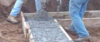
After the work has been completed, concrete can be laid. Please note that the concrete mixture must be of high quality and reliable. Choose concrete of a grade not lower than M200 B15. If you want to make the solution yourself, mix cement, sand and crushed stone in a ratio of 1:3:5. Dilute the mixture with water in a ratio of 60% of cement.
Concrete should be laid gradually in even layers of equal composition. After pouring, the concrete surface is covered with film or cloth and left until completely hardened. In dry weather, you should periodically water the concrete.
During operation, cracks and crevices may appear on the blind area. Such defects are eliminated using liquid cement mortar. Large cracks that occupy a large area are cut down to their full depth and cleaned of dirt. Then the holes are filled with mastic and sprinkled with sand on top. Significant deficiencies are restored using fresh concrete.
Design of the blind area
Calculation of the bearing capacity of centrally compressed elements of stone structures.
Calculation of elements of unreinforced masonry structures under central compression is carried out according to the formula
,
where N
— design longitudinal force;
R
is the calculated compressive strength of the masonry;
φ
—buckling coefficient;
A
— cross-sectional area of the element;
m q
– coefficient taking into account the duration of the load.
R
The calculation (selection of the cross-section) of the centrally compressed element (column) according to formula (4.1) is carried out by the method of successive approximation and is as follows:
a) the loads for the calculated column N and Ng are determined (at the level of a particular floor), calculating them as the sum of the loads from all floors lying above the calculated section of the column with an approximate account of the column’s own mass as a load constituting 5...10% of the calculated one;
b) the masonry material is selected (type and brand of stones and type and brand of mortar) and its design resistance R is assessed;
c) a certain value φ is specified, from which the corresponding values λh (λi) are taken;
d) based on the found flexibility λh (λi), the coefficient η is determined;
e) using the loads N and Ng pre-assembled on the column, the coefficient mg is determined;
f) using formula (4.1), the cross-sectional area of the column A is calculated
,
corresponding to the masonry material and the accepted coefficient φ at a given load;
g) value A from formula (4.2) is expressed through the specific dimensions of the cross section of the column hxb = A, if the column is rectangular, or hxh = A, if the column is square, rounding them to values that are multiples (taking into account the thickness of the masonry joints) to the dimensions of the brick (stone ) in respect of;
h) based on the accepted geometric dimensions of the cross section of the column, the elastic characteristic of the masonry α and the calculated height of the column, its flexibility λh (λi) is calculated;
i) find the coefficients φ and η corresponding to λh (λi) according to item h) and determine the coefficient mq;
j) the obtained values of φ and mg, more precisely the product of these coefficients φ·mg, are compared with the original one. If the resulting product (φ·mg)pol differs from the original (φ·mg)ref by more than 5%, i.e. there is inequality
,
then the calculation should be repeated, taking the obtained values of φ and mg as the initial ones.
The calculation is considered complete when the inequality is satisfied
.
ABOUT
the final dimensions of the cross section of the column correspond to the last value (φ·mg)ref in the described process of successive approximation.
It is more convenient to start the process of successive approximation with φ=1.0. In this case, η=0 and mg out=1.0. The condition mg=1.0 should also be taken into account if h≥30 cm or i≥8.7 cm.
Calculations show that, as a rule, 1-2 approximations are sufficient to satisfy inequality (4.4).
Strength of masonry in tension, shear and bending.
Standard and design resistances of masonry.
Tensile strength of masonry
The strength of masonry when working in tension, shear and bending depends mainly on the amount of adhesion between the mortar and the stone.
There are two types of adhesion: normal - S (Fig. 10.9, a) and tangent - T (Fig. 10.9, b).
Experiments have shown that tangential adhesion is twice as high as normal, that is, T=2·S.
Adhesion increases over time and reaches 100% after 28 days.
In vertical joints of masonry, due to shrinkage of the mortar during hardening, its adhesion to the stone is significantly weakened or completely broken on one of the adjacent side surfaces of the stone.
Therefore, in the calculations, adhesion in vertical joints is not taken into account, and only adhesion in horizontal joints of masonry is taken into account.
According to tangential and normal adhesion, two types are distinguished
stretching of masonry: stretching along an untied and tied seam.
Fig.10.9
Rice. 10.10. The work of masonry made of stones of the correct shape in tension:
a - for unligated sections (cases 1-4); b - along bandaged sections; c - on untied
sections under eccentric compression
Shear strength of masonry
The tensile strength of masonry when cut along untied sections is determined by
Coulomb's law (Fig. 10.11a), according to which
ср = сс + ƒ·
where sc is tangential cohesion (sc = 2 · sc, sc is normal cohesion);
ƒ – coefficient of friction in the joints of the masonry, equal to: 0.7 – for masonry made of solid bricks
and stones of regular shape; 0.3 – for masonry made of hollow bricks and stones with
vertical voids; – average normal compressive stress at the lowest longitudinal force.
Rice. 10. 11. Cutting a masonry of stones of the correct shape:
a – for unligated sections; c, d – cut along the untied seam in the masonry of the retaining wall and in the heel of the arch; d – cut of masonry along the tied seam in the cantilever overhang
Strength of masonry in bending
Bending in masonry causes tension, which determines strength
masonry in a stretched area.
Mel = t = t(10.4)
In fact, due to the fact that in masonry, in addition to elastic, there are also
plastic deformations, the diagram of normal stresses is curvilinear (Fig. 10.12, b) and, if we take it rectangular (which is very close to the actual diagram), we obtain:
Mpl = t= t(10.5)
that is, 1.5 times more than with elastic work. In practical calculations they use
formulas for the strength of materials and the moment of resistance W are determined as for
elastic material. Calculated tensile strength of masonry when bending along
bandaged section, Rtb is taken to be approximately 1.5 times greater than the calculated one
resistance of masonry in central tension Rt.
Kinds
Thermal seams must be made strictly in accordance with SNiP regulations.
There are several types of seams that increase the resistance of a structure to various factors affecting its durability:
Temperature connections provide reliable protection of walls from the negative effects caused by changes in ambient temperatures. Their design complies with SNiP II-22-81 regulations, paragraphs 6.78-6.82.
Their peculiarity is that such seams are arranged in accordance with the height of the walls, without affecting the foundation.
A brick wall at a temperature of +20°C in the hot season and -18°C or lower during the winter cold expands and contracts. Its height changes accordingly.
Settlement joints help the building to withstand heavy loads
Settlement joints are designed to protect the load-bearing walls of a building from deformation and premature destruction under the influence of increased loads. It is these loads that lead to uneven shrinkage of the building and the appearance of cracks on the walls.
These defects most often occur during the construction of multi-story buildings. Sedimentary expansion joints begin to form from the foundation of the house.
Anti-seismic seams are those whose installation is mandatory in areas with increased seismic hazard. Soil mobility and tremors lead to significant deformations, which result in cracking of walls and their subsequent destruction. The peculiarity of such seams is that with their help the building seems to be divided into separate stable blocks.
The quality of the joint filling determines the building’s ability to withstand deformation, its reliability and durability.
Classification of commonly used types of expansion joints
- Insulating. The main task of the insulating seam is to prevent the transfer of deformation forces from capital objects to the floor screed. In accordance with this task, there are the following types of location of insulating seams: along the walls, along the perimeter of the columns, along the perimeter of the foundation. The technology for creating an expansion joint of this type consists in laying a special material around the perimeter of a particular structure before pouring concrete;
- Shrink seam. As is known, setting and hardening of concrete occurs unevenly. The upper layers set and dry quickly, while the deeper layers dry relatively slowly. As a result, internal stresses arise, causing the formation of cracks. To prevent this phenomenon, so-called “shrinkage seams” are cut. The seams are located along the axes of the columns and join the corners of the elements located along the perimeter. The depth of the “cut” should correspond to 30% of the thickness of the floor screed. The actual “cutting” is done using special equipment or by installing special slats at the pouring stage;
- Structural expansion joints . This type of joint is installed in the place where the day shift or portion of laying screed on a concrete site ends. Typically, a structural expansion joint consists of a thin strip of wood, a strip of glass, or a layer of soft bitumen. It should be borne in mind that an expansion joint of this type “works” as a shrinkage joint, smoothing out small horizontal movements of individual parts of the concrete structure.
Device
The most common is a temperature expansion joint, since significant temperature changes become one of the most common reasons why building walls crack and collapse. The width of the seam being made depends on the temperature level.
In accordance with the regulations, it cannot be less than 2 cm, and in some cases reaches 3 cm. This is due to the fact that expansion joints have sufficient horizontal mobility. The distance between the joints is no less than 15 and no more than 20 m. In the hottest areas, this distance can be reduced to 10 m. For more information about the need for brickwork joints, see this video:
The design is easy to install. The work is done using:
- tourniquets;
- elastic fillers, characterized by their ability to retain elasticity after hardening;
- bentonite or other substances containing a small percentage of concrete;
- sealants with increased elasticity.
The construction of the expansion joint begins during the construction of the house. To do this, it is enough to retreat the required distance from the main masonry and fill it with insulation or sealant. The installation process will be easier if the depth of installation of the sealant is small.
Expansion joint between buildings
What are the types of expansion joints between buildings? Experts classify them according to a number of characteristics. This may be the type of structure being serviced, the location (device), for example, expansion joints in the walls of the building, in the floors, in the roof. In addition, it is worth considering the openness and closedness of their location (indoors and outdoors, outdoors). A lot has already been said about the generally accepted classification (the most important, covering all the most characteristic signs of expansion joints). It was adopted on the basis of the deformations that it is intended to combat. From this point of view, the expansion joint between buildings can be temperature, sedimentary, shrinkage, seismic, or insulating. Depending on the current circumstances and conditions, different types of expansion joints are used between buildings. However, you should know that all of them must correspond to the initially specified parameters.
Even at the building design stage, specialists determine the location and size of expansion joints. This occurs taking into account all expected loads causing deformation of the structure.
When constructing an expansion joint, it is necessary to understand that it is not just a cut in the floor, wall or roof. With all this, it must be correctly designed from a constructive point of view. This requirement is due to the fact that during the operation of structures, expansion joints take on enormous loads. If the load-bearing capacity of the seam is exceeded, there is a risk of cracks. This, by the way, is a fairly well-known phenomenon, and special profiles made of metal can prevent it. Their purpose is expansion joints - profiles seal them and provide structural reinforcement.
The seam between buildings serves as a kind of connection between two structures that are close to each other, but have different foundations. As a result, the difference in the weight load of the structures may have a negative impact, and both structures may develop unwanted cracks. To avoid this, a rigid connection with reinforcement is used. In this case, it is necessary to make sure that both foundations have already settled properly and are sufficiently resistant to the upcoming loads. The construction of the expansion joint is carried out in strict accordance with generally accepted procedures.
Waterproofing of brickwork main types
Structures made of brick are characterized by high strength and are resistant to temperature changes, but they can collapse under the influence of moisture.
That is why the importance of waterproofing brickwork is difficult to overestimate. The modern selection of moisture-proof materials allows the use of those compositions that can provide maximum results. Let's consider the main types and methods of application: - painting waterproofing. We clean the surface of debris, dry it and prime it. Next, apply several layers of waterproof compound. The quality and service life of the insulation depends on how smooth and continuous the layer is. Therefore, all defective areas should be processed several times. These can be bitumen emulsions, pastes, mastics, bitumen-polymer, polymer-cement compositions. Hot compositions have increased frost and moisture resistance. Cold mastics, pastes and emulsions may develop cracks when frozen; — simultaneous application of horizontal and vertical waterproofing of brickwork. This method uses a solution of cement or asphalt or roll insulation. A layer of screed is applied to the foundation slab and walls, followed by masonry. If you use a roll method of protection from moisture, then pasting should be carried out in stages. We apply a layer of mastic to the surface, then a layer of material (for example, roofing felt), then a second layer of mastic and the next layer of rolled material. We clean the vertical surface from dust and soil and roll it with mastic; we glue the layers overlapping with horizontal insulation, so that subsequently moisture cannot penetrate into the joints. — penetrating protection against moisture. The penetrating composition forms crystals in the pores of the building material, which reliably block the access of moisture inside the structure, but do not impede air circulation. Penetrating compounds are applied to a brick wall using a special technology: - grooves are created in masonry joints to 2/3 of the masonry thickness using a chisel and a hammer drill; — the grooves are cleaned and washed; — a penetrating compound is placed into the seams; — a penetrating mixture (waterproofing plaster) is applied to the entire surface of the wall in several stages. Over the next 3 days, it is necessary to constantly moisturize. The plaster is reinforced using fiberglass mesh, which is subsequently impregnated with a special alkali-resistant compound. The thickness of the insulation layer reaches 30 mm; — injection waterproofing. It is a type of penetrating moisture protection, characterized by high technical qualities and durability. The materials used are liquid rubber or liquid glass. Liquid glass is added to concrete mortar or used in its pure form. Liquid rubber is applied by spraying.
High-quality waterproofing of expansion joints and brickwork will reliably protect the house from moisture, eliminate the risk of corrosion of reinforcement used in reinforced concrete foundations, increase the chemical resistance of building materials, and prevent the formation of mold and mildew in the house.
Depending on the specific purpose, joints in industrial floors are divided into:
- Shrinkage (compensation). Help prevent the formation of cracks throughout the concrete base as a result of shrinkage of the material.
- Insulating. They protect the base from the deformation effects of other structural elements: walls, columns, foundations for equipment.
- Structural. They are located in places where concreting maps join.
Let's take a closer look at how each type is performed and why you need to cut them.
Shrinkage
Shrinkage is performed on a concrete base 2-3 days after laying the material. They are cut to a depth of 1/3 of the layer thickness using a special machine in the form of cards 3 by 3 or 6 by 6 meters. A rectangular shape is also allowed, but the ratio of length to width should not exceed 2:1.
An important rule to consider when cutting: the maximum length of the card is equal to the thickness of the slab multiplied by 30!
Why are shrink joints needed in the floors of industrial buildings? They prevent widespread cracks in the material. The fact is that concrete dries unevenly. Initially, moisture evaporates from its upper layers, the lower ones harden much more slowly. The difference in drying speed creates tension. To prevent cracks from spreading over the entire area, cutting is carried out. During the hardening process, the joints move apart, as a result, the stress is compensated.
Insulating
This type is performed along the structural elements of the building: walls, columns, foundation for equipment. The concrete is cut through its entire thickness. Insulating expansion joints are especially important on objects subject to temperature fluctuations and mechanical loads. Another factor is ground movement. If there are expansion joints, the deforming effects from the walls will not be transferred to the concrete screed.
Structural
The next type is structural. They are cut at the boundaries of concreting maps. In another way they are called “cold”. It is almost impossible to lay a concrete screed over a large area without structural joints. Once the card area is covered, the material on the surface begins to set. If you lay a fresh screed end-to-end the next day, cracks may appear. Therefore, after stopping work, structural expansion joints should be made in the floors of industrial buildings. The position of all joints on the site must be agreed upon in advance.
Expansion joints
6.78.
Temperature-shrinkage joints in the walls of masonry buildings should be installed in places of possible concentration of temperature and shrinkage deformations, which can cause masonry ruptures, cracks, distortions and shifts of masonry at seams that are unacceptable under operating conditions (at the ends of extended reinforced and steel inclusions, as well as in places significant weakening of walls by holes or openings). The distances between temperature-shrinkage seams must be established by calculation.
6.79.
The maximum distances between temperature-shrinkable joints that can be taken for unreinforced external walls without calculation:
a) for above-ground stone and large-block walls of heated buildings with the length of reinforced concrete and steel inclusions (lintels, beams, etc.) not exceeding 3.5 m and the width of the partitions not less than 0.8 m - according to table. 32; if the length of inclusions is more than 3.5 m, the masonry sections at the ends of the inclusions must be checked by calculation for strength and crack opening;
b) the same for walls made of rubble concrete - according to table. 32 as for masonry made of concrete stones using mortar grade 50 with a coefficient of 0.5;
c) the same, for multi-layer walls - according to table. 32 for the material of the main structural layer of the walls;
d) for walls of unheated masonry buildings and structures for the conditions specified in paragraph “a” - according to table. 32 with multiplication by coefficients:
for closed buildings and structures - 0.7
for open structures - 0.6
e) for stone and large-block walls of underground structures and foundations of buildings located in the zone of seasonal soil freezing - according to Table. 32 with double magnification; for walls located below the limit of seasonal soil freezing, as well as in the permafrost zone - without length limitation.
Table 32
| Distance between expansion joints, m, when laying | ||||
| Average outside air temperature of the coldest five-day period | from clay bricks, ceramic and natural stones, large blocks of concrete or clay bricks | from sand-lime brick, concrete stones, large blocks of sand-lime concrete and sand-lime brick | ||
| on brand solutions | ||||
| 50 or more | 25 or more | 50 or more | 25 or more | |
| Minus 40°C and below | 50 | 60 | 35 | 40 |
| Minus 30°C and below | 70 | 90 | 50 | 60 |
| Minus 20С and above | 100 | 120 | 70 | 80 |
| Notes: 1. For intermediate values of design temperatures, the distances between expansion joints may be determined by interpolation. 2. The distances between temperature-shrinkage joints of large-panel buildings made of brick panels are assigned in accordance with the instructions for designing structures of large-panel residential buildings. |
6.80.
Expansion joints in walls connected to reinforced concrete or steel structures must coincide with the joints in these structures. If necessary, depending on the structural design of buildings, additional expansion joints should be provided in the masonry walls without cutting reinforced concrete or steel structures with seams in these places.
6.81.
Settlement joints in the walls must be provided in all cases where uneven settlement of the base of a building or structure is possible.
6.82.
Expansion and settlement seams should be designed with a tongue or groove filled with elastic gaskets, eliminating the possibility of blowing through the seams.
Shrink seam
The shrinkage seam fragments the structure (slab), while the cut is never brought to the bottom edge of the slab. Shrinkage stresses in concrete are high, and if the slab is not unloaded, the concrete will not only crack, but may become unsuitable for further use (or require complex expensive repairs, installation of packers and injections) due to a number of deep through cracks in stressed areas. The shrinkage cut is made according to calculation - for part of the height of the slab, thereby weakening the working section. “Where it is thin, it breaks”: the shrinkage crack will predictably go into the depth of the cut and will not reach the sealed surface of the structure. Shrinkage seams are often combined with other seams; in these cases there may be no cracks or breaks. Shrinkage joints are deformation compensators in reinforced concrete structures. Thanks to shrinkage seams, shrinkage deformations are compensated. For example, when a concrete screed sets, due to physical factors it cannot harden and lose moisture completely evenly. The screed is cut into cards - squares of the calculated area (in the simplest cases for reinforced screeds these are 6 * 6 m cards; if the size of the screed is smaller, a seam is not needed), and the provided cuts eliminate the appearance of unintended cracks.
Insulation and insulation options
In order to protect against environmental influences and prevent drafts inside the building, all deformation gaps without exception are insulated. To do this, create a protective sealed layer using elastic materials. The choice of insulation depends on the size of the expansion joint. In this case, one type of material or a combination of them is used. The table shows the type of insulation depending on the width of the temperature gap in the brickwork:
| Seam width, mm | Insulation | |
| up to 30 | Polyurethane foam | |
| over 30 | Vilaterm | Polyurethane foam |
| Expanded polystyrene |
To seal insulated seams use:
- two-component sealant;
- galvanized expansion joint.
Polyurethane sealant is used because it has a long service life and a high level of flexibility of the sealing layer. Strengthening and sealing the joint with a galvanized expansion joint with a deformation bend will last a longer period. Its durability is determined by the aging period of the metal. In case of damage to the tightness of the expansion joint or its insulation, repair work is carried out.
How to make expansion or shrinkage seams correctly
Now directly about the execution of work. As you can see, their design is almost not specified in the standards. It is difficult to find literature on this issue. Therefore, we will give practical advice based on existing projector documentation and building designs.
Location of shrink seams
Everything is clear with the location of the temperature expansion joints; the maximum distances between them are taken according to SNiP (you can take less, but why).
But the question arises - where to arrange shrinkage seams? Sometimes it becomes clear that we cannot do without them, the soil is weak and cracks are visible on many nearby buildings, which means that our house may find itself in a similar situation.
It’s clear that no one will study geology and carry out calculations if we build a house with our own hands. Let's move away from SNiP (if cracks appear in your personal building because of this, then no one will punish you for it) and arrange them without calculations.
It’s easy to decide where to make seams - look where shrinkage cracks most often form in houses, usually at a distance of 1-2 meters from the corners. There we will make shrinkage seams.
Cracks in brickwork due to shrinkage usually form at a distance of 1-2 m from the corner
For large buildings, it is also advisable to additionally make a seam in those places where the structure and properties of the soil clearly change. For example, at the border of natural and bulk soil.
Shrinkage joints should be made in places where the soil can sag
How wide should the seams be?
There is not a word about this in the norms either. But almost always the seam width is chosen to be 10-20 mm. If you use special joint profiles for sealing, then select this value in accordance with the width of the profile.
We arrange the seams
As already mentioned, the seams should have a quarter or groove profile. When doing masonry this is not difficult to do in most cases.
- If the wall is a quarter or half brick, then you will have to hew or cut the bricks, choosing a quarter or tongue and groove profile in them. This is time-consuming but, as a rule, such thin masonry is not used for load-bearing walls that require the creation of shrinkage and expansion joints.
- With a brick wall, we achieve the quarter effect using ordering - in the area of the seam it will look something like this.
Temperature deformation (shrinkage) joint when laying in bricks When
making expansion joints, it is desirable that the mortar squeezed out when installing the brick does not get into it and accidentally connect the rows on both sides. Therefore, we distribute it so that on the edges of the bricks facing the seam, we get a “waste area”.
Also, if you want the seams not to stand out on the wall surface, you can make them not in the form of vertical lines, but in a zigzag in accordance with the vertical order. This makes it easier to do the laying, but then it will be more difficult to fill the seams with insulating material.
Option for making a seam while maintaining the order
Seams in masonry that was laid previously
A manual seam cutter, which can be used to make a shrink seam in a ready-made wall, usually has a small diameter disk and will not be able to cut through a thick wall.
This option is also possible. When the foundation settles, instead of strengthening it (especially in weak soils), you can simply make shrinkage joints. This approach is possible in principle, although its implementation will cause difficulties.
You can cut through a wall one and a half to two bricks thick with a large-diameter disk, and seam cutters with such a working tool are, as a rule, designed to work on horizontal surfaces (floors and roads) and not on vertical ones.
More powerful models can only work on horizontal surfaces
Paper beacons on a crack
Temperature expansion joints in concrete floors and cement-sand screeds
A foundation deck is a laid strip of the foundation of a house that serves to protect it from external sources of moisture, such as rain and flood waters. In addition, it protects the soil around the perimeter of the foundation from erosion, since if it is not done, the water that flows from the roof and walls of the house during precipitation will immediately fall into the soil surrounding the foundation.
Scheme of the blind area at the TISE foundation.
The foundation is protected from various materials, but the structure remains unchanged, consisting of an underlying and waterproofing layer. The base is the underlying layer, on top of which a waterproofing layer is laid. When constructing the base, crushed stone and sand are most often used. The top layer will be waterproofing. It serves as an obstacle to water entering the near-foundation soil.
The blind area is made of clay, concrete, asphalt or paved with stone.
Foundation protection
The most economical and simplest option for foundation protection is using clay, which simultaneously serves as an underlying and waterproofing layer. The clay is compacted thoroughly. You can lay a lawn on top of the clay or pour sand or crushed stone, which can protect the surface from erosion.
Shock-absorbing cushion diagram: 1 – drainage pipes; 2 – ring cushion; 3 – asphalt; 4 – waterproofing; 5 – wall; 6 – crushed stone backfill; 7 – sand; 8 – sand cushion.
Asphalting is often done. For the base of such foundation protection, gravel is used, on which 3 cm thick asphalt is laid. A relatively simple option, more expensive than clay, but well resistant to moisture.
The most thorough solution is concrete protection. In this case, gravel is also used. The blind area can be reinforced monolithic or made of separate slabs. But here it is important to correctly carry out all concrete work, taking into account expansion joints between certain areas and between the blind area and the foundation of the house itself. If such important points are not provided for, under the influence of frost heaving, deformation may occur, and the blind area will move away.
Regardless of the method of execution, an expansion joint of about 10-20 mm wide is made between the foundation and the blind area.
Such a seam can be made from a layer of extruded polystyrene foam or sand. If you perform a continuous pour with the foundation, then when the soil heaves, the blind area may move away, develop cracks and even damage the lining of the base.
In reinforced concrete building structures, the dimensions of floors, as well as the dimensions of other elements, can vary depending on temperature changes. Therefore, when installing them, it is necessary to arrange expansion joints.
The materials for their manufacture, dimensions, locations and installation technology are indicated in advance in the design documentation for the construction of the building.
Sometimes such seams are structurally made to be sliding. To ensure sliding in those places where the floor slab rests on the supporting structures, two layers of galvanized roofing iron are laid under it.
When pouring a cement-sand screed or arranging a concrete floor, it is necessary to isolate all building structures (walls, columns, doorways, etc.) from contact with the poured mortar throughout its entire thickness. This gap performs three functions simultaneously:
- At the stage of pouring and setting the mortar works as a shrinkage joint. The heavy wet solution compresses it; as the concrete mixture gradually dries, the dimensions of the poured canvas decrease, and the material filling the gap expands and compensates for the shrinkage of the mixture.
- It prevents the transfer of loads from building structures to the concrete surface and vice versa. The screed does not put pressure on the walls. The structural strength of the building does not change. The structures themselves do not transfer the load to the screed, and it will not crack during operation.
- When there is a temperature difference (and they necessarily occur even in heated rooms), this seam compensates for changes in the volume of the concrete mass, which prevents it from cracking and increases its service life.
We suggest you familiarize yourself with How to properly make a blind area around a house on a slope.
To create such gaps, a special damper tape is usually used, the width of which is slightly greater than the height of the screed. After the solution has hardened, its excess is cut off with a construction knife. When shrinkage joints are installed in concrete floors (if a finishing floor covering is not provided), the polypropylene tape is partially removed and the groove is waterproofed using special sealants.
In rooms of a large area (or when the length of one of the walls exceeds 6 m), according to SNiP, it is necessary to cut longitudinal and transverse temperature-shrinkage joints with a depth of ⅓ of the thickness of the fill. Expansion joints in concrete are made using special equipment (gasoline or electric joint cutter with diamond discs). The pitch of such seams should not be more than 6 m.
Attention! When filling heated floor elements with mortar, shrinkage joints are installed to the entire depth of the screed.
Foundation blind areas, designed to protect the foundation of a house from the harmful effects of precipitation, are also susceptible to destruction due to significant temperature changes throughout the year. To avoid this, seams are installed to compensate for the expansion and contraction of concrete. Such gaps are made at the stage of construction of blind area formwork.
All of the above also applies to the arrangement of concrete paths on the street or parking spaces near your own home. However, the step of deformation gaps can be increased to 3÷5 m.
Types of expansion joints in a brick multi-storey building
In the group of such sutures there is a sedimentary type.
In addition to temperature ones, there are other types of expansion joints in masonry, such as:
- shrinkage;
- sedimentary;
- seismic.
All types of special gaps protect each structural unit of the house from destruction and prevent the formation of cracks in load-bearing and other walls. Temperature and shrinkage voids are made in all brick houses without exception. Sedimentary ones perform a protective function against destruction under high loads and are needed in multi-storey buildings and houses with an extension. They are made starting from the foundation, but the device is made on the principle of vertical temperature gaps, so it is possible to combine them into heat-shrinkable ones and create them in one firmware. It is advisable to create seismic voids only in areas with increased seismic activity.
Temperature seam
How to create an expansion joint? For this you will need:
- perforator;
- roofing felt;
- tow;
- clay castle (clay, sand, water, straw).
This type of protection is provided for in the horizontal projection even during brick laying and is necessarily indicated in the house design. To equip it, a tongue and groove is used in the masonry, which is covered with two layers of roofing felt, then covered with tow and coated with a clay castle on top.
A tongue and groove is created in the masonry during construction, but if this was not provided for, but the work needs to be done, then you can organize it yourself using a hammer drill, but this should be done extremely carefully. A tongue and groove is a recess in something (for example, a brick wall), which is used to attach a part that has a reverse structure
Such recesses are always horizontal. A tongue and groove is made 2 bricks high and with a depth of 0.5. It is covered with two layers of roofing felt, and tow is driven inside. Due to their properties, they do not react to temperature changes and will not allow a brick wall to react to them.
At the final stage, expansion joints should be coated. Many people use cement mortar, but a clay castle will be much more effective, because... has three necessary functions at once: decorative (with brickwork, such a castle will not attract unnecessary attention), thermal insulation (clay perfectly holds any temperature, and clay houses are compared to thermoses), waterproofing (a clay castle will not allow moisture to pass through and will not get wet, no matter what It happened). Such a seam can be done quite carefully, after which it will no longer be necessary to cover it to create a design.
